Method and device for measuring gas component concentration inside a glass unit

a technology of gas component and glass unit, which is applied in the direction of material analysis, instruments, spectral investigation, etc., can solve the problems of invasive methods, inability to directly access conductivity measurement, and broken glass unit surfa

Active Publication Date: 2014-04-03
SPARKLIKE
View PDF1 Cites 7 Cited by
  • Summary
  • Abstract
  • Description
  • Claims
  • Application Information

AI Technical Summary

Benefits of technology

[0007]An object of the invention is to alleviate and eliminate the problems relating to the known prior art. Especially the object of the invention is to provide a method for performing a non-invasive determining a concentration of a gas component in a gas mixture contained in a spacing of a glass unit independently of possible coating material. An additional object of the invention is to provide a method for determining a concentration of gas components in each spacing separately at a same time.

Problems solved by technology

Since the low emissivity coating is typically inside an insulating glass unit for mechanical and chemical protection, it cannot be directly accessed for conductivity measurement.
Taking the gas sample is invasive method, whereupon the surface of the glass unit must be broken, which is clear disadvantage of the invasive methods.
There are also some drawbacks with the known non-invasive methods.
In addition when at least one sheet has a metallically coated surface, the measurement cannot be done through the metallic surface, since the rapidly alternating electrical field cannot penetrate the metallic surface.

Method used


Image

  • Method and device for measuring gas component concentration inside a glass unit
  • Method and device for measuring gas component concentration inside a glass unit
  • Method and device for measuring gas component concentration inside a glass unit

Examples


Embodiment Construction

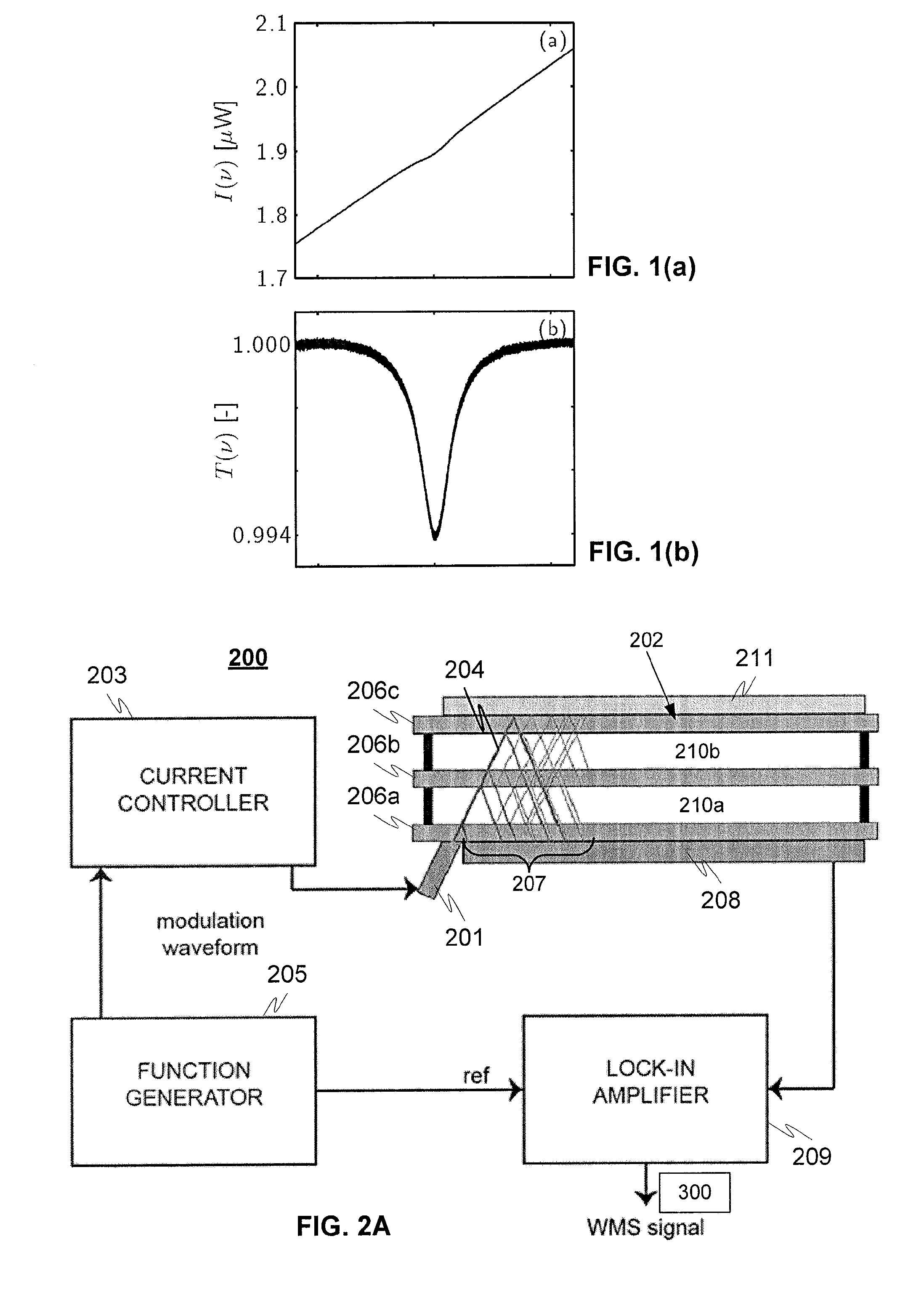
[0062]FIGS. 1(a) and 1(b) relates to measurements and phenomena known from prior art, and are discussed earlier in this document.

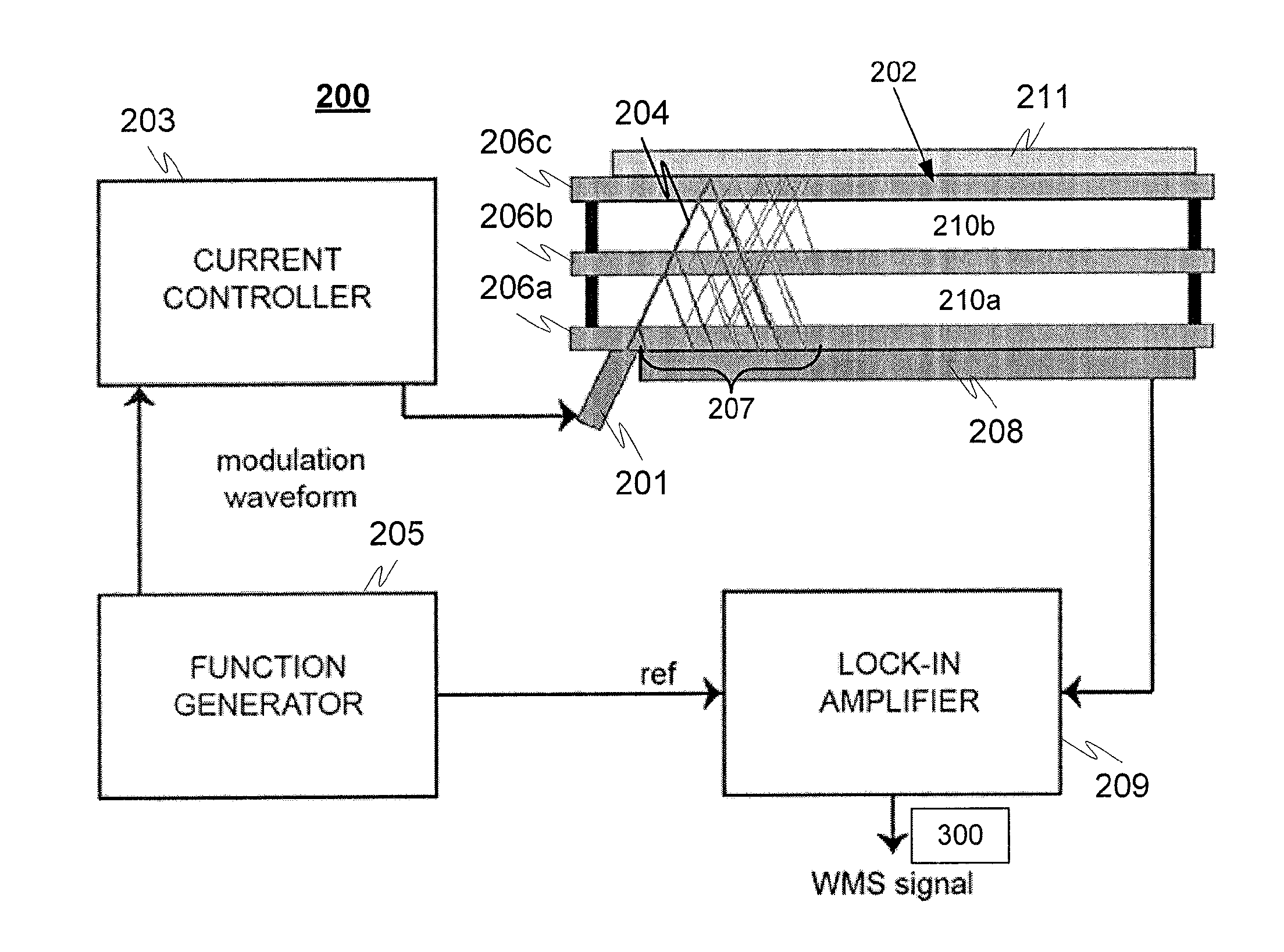
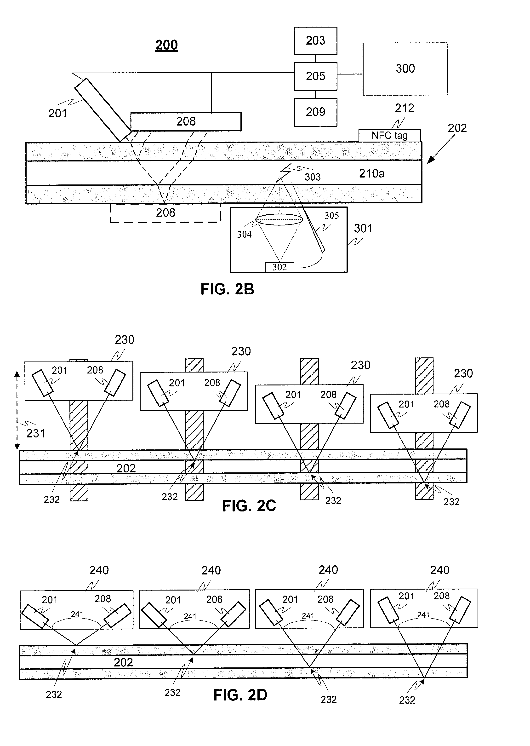
[0063]FIGS. 2a-2e illustrates principles of exemplary measuring constructions 200 for determining a gas component concentration inside a transparent structure according to an advantageous embodiment of the invention.

[0064]According to an embodiment of the invention an apparatus comprises a light source 201 for emitting at least one light beam to the surface of the object, such as a glass unit 202. The light source is advantageously a narrow-band light source, which could be e.g. Vertical Cavity Surface Emitting Laser (VCSEL). The wavelength of emitted laser may be controlled e.g. by current by an adjustable current source 203. According to an embodiment the laser beam emitted 204 is modulated by introducing a modulation waveform to the current controller of the laser source (e.g. by WMS technique). For example an arbitrary waveform generator 205 can be use...


PUM

PropertyMeasurementUnit
concentrationaaaaaaaaaa
wavelengthaaaaaaaaaa
concentrationsaaaaaaaaaa

Abstract

A non-invasive method for determining a concentration of a gas component in a gas mixture contained in a spacing of a glass unit having at least two glass sheets spaced apart from each other and forming the spacing. One or more light beams is applied at an angle to the surface of the glass unit, wherein the wavelength of the emitted light beam is varied around or over the at least one absorption line of the interest gas component. The light beams transmitted through or reflected from at least one surface or interface locating at the opposite side of the spacing are collected by a detector and non-linear variations in the intensity of the transmitted or reflected light beams over an absorption line of the interest gas is then component determined. The concentration of the gas component to be measured is determined based on the non-linear variations in the intensity.

Description

TECHNICAL FIELD OF THE INVENTION[0001]The invention relates to a method and device for measuring a gas component concentration inside a glass unit of one or several separate cavities or any other similar transparent container. In addition the invention relates to measuring the glass unit of one or several separate cavities or any other similar transparent container dimensions, laminations and metallic coatings.BACKGROUND OF THE INVENTION[0002]In the glass manufacturing process glass sheets (known as float glass) can be combined with different kind of elements, such as coated or tempered layers to create glass panes for different purposes having specific properties. For example, insulating glass units, IGUs, are constructed typically with a configuration having two or more glass sheets with a closed spacing in between the sheets, where the closed spacing is filled with gas with low thermal conductivity, such as Oxygen, Argon, Xenon, Krypton Nitrogen or mixture of those.[0003]In addit...

Claims


Application Information

Patent Timeline
Patent Type & Authority Applications(United States)
IPC IPC(8): G01N21/61G01B11/06G01J3/443G01N21/55
CPCG01N21/61G01J3/443G01B11/06G01N21/55G01N21/031G01N21/39G01N21/67G01N2021/0396
Inventor NIIRANEN, KAILAUNO, ERNO
Owner SPARKLIKE
Why Eureka
Try Eureka