Eureka AIR delivers breakthrough ideas for toughest innovation challenges, trusted by R&D personnel around the world.

Forward osmosis membrane flow system and composite semipermeable membrane for forward osmosis membrane flow system

a technology of forward osmosis membrane and flow system, which is applied in the direction of machine/engine, filtration separation, separation process, etc., can solve the problems of large amount of energy required and system using these membranes as forward osmosis membranes do not have a sufficiently high efficiency, so as to achieve high permeation flux, increase efficiency, and high permeation flux

Inactive Publication Date: 2014-04-24
NITTO DENKO CORP
View PDF4 Cites 8 Cited by
  • Summary
  • Abstract
  • Description
  • Claims
  • Application Information

AI Technical Summary

Benefits of technology

The forward osmosis membrane flow system described in this patent text uses a composite semipermeable membrane with a polyamide-based skin layer on top of a porous epoxy resin membrane. This results in a high permeation flux of fluid moving through the membrane, making the system more efficient. Using this composite membrane in the flow system increases the amount of fluid that can be moved, resulting in a higher efficiency of the system.

Problems solved by technology

Particularly, in a seawater desalination process using a reverse osmosis membrane, freshwater that is necessary for human life is produced from seawater while generally it is necessary to apply energy of at least osmotic pressure of the seawater and therefore a large amount of energy is required.
Therefore, systems using these membranes as forward osmosis membranes do not have a sufficiently high efficiency.

Method used


Image

  • Forward osmosis membrane flow system and composite semipermeable membrane for forward osmosis membrane flow system
  • Forward osmosis membrane flow system and composite semipermeable membrane for forward osmosis membrane flow system

Examples


example 1

(Production of Porous Epoxy Resin Base Material)

[0069]An epoxy resin composition was prepared with 139 parts by weight of bisphenol A type epoxy resin (Epicoat 828, manufactured by Japan Epoxy Resins Co., Ltd.), 93.2 parts by weight of bisphenol A type epoxy resin (Epicoat 1010, manufactured by Japan Epoxy Resins Co., Ltd.), 52 parts by weight of bis(4-aminocyclohexyl)methane, and 500 parts by weight of polyethylene glycol 200 (manufactured by Sanyo Chemical Industries, Ltd). A cylindrical mold (with an outer diameter of 35 cm and an inner diameter of 10.5 cm) was filled with the epoxy resin composition up to a height of 30 cm, which was then room-temperature cured at 25° C. for 12 hours and further was allowed to reaction-cured at 130° C. for 18 hours. Thus, a cylindrical resin block was produced. While being rotated around the cylindrical axis, the resin block was sliced continuously at a thickness of 145 μm from the surface thereof using a cutting device (manufactured by Toshiba ...

example 2

[0072]A composite semipermeable membrane of Example 2 was obtained in the same manner as in Example 1 except that the cutting thickness of the resin block was changed to 90 μm in producing the porous epoxy resin membrane. The composite semipermeable membrane according to Example 2 thus finally obtained had a thickness of 80 μm.

example 3

[0073]A composite semipermeable membrane of Example 2 was obtained in the same manner as in Example 1 except that the cutting thickness of the resin block was changed to 55 μm in producing the porous epoxy resin membrane. The composite semipermeable membrane according to Example 3 thus finally obtained had a thickness of 50 μm.


PUM

PropertyMeasurementUnit
thicknessaaaaaaaaaa
osmotic pressureaaaaaaaaaa

Abstract

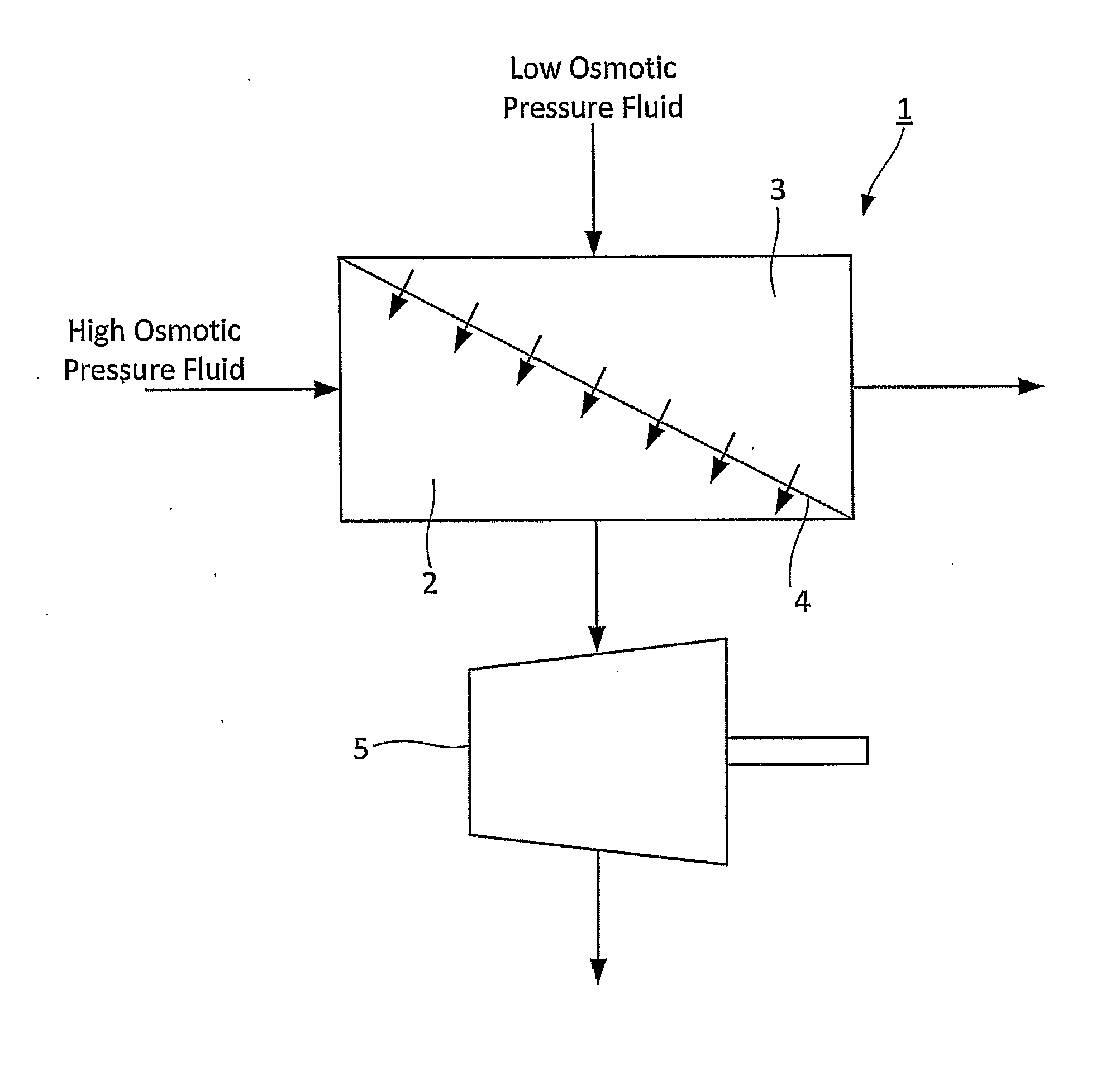
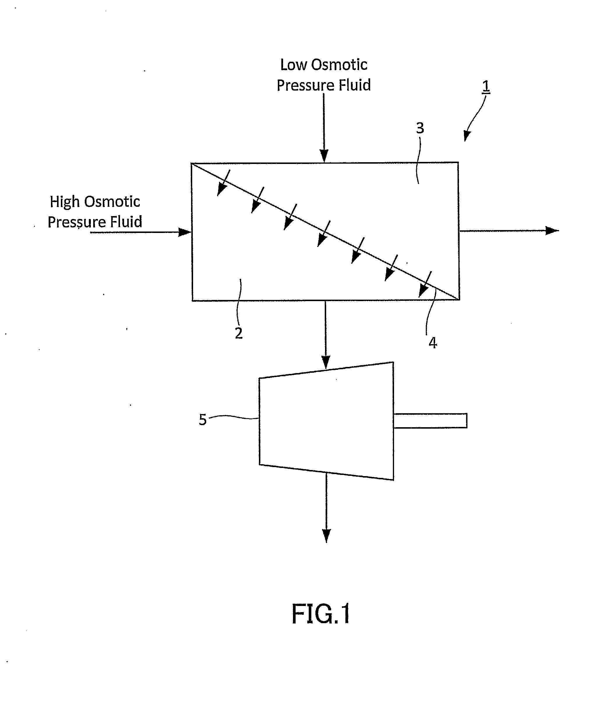
The forward osmosis membrane flow system (1) includes a high osmotic pressure fluid flow section (2) to which a high osmotic pressure fluid is supplied, a low osmotic pressure fluid flow section (3) to which a low osmotic pressure fluid with a lower osmotic pressure than that of the high osmotic pressure fluid is supplied, and a semipermeable membrane (4) that separates the high osmotic pressure fluid flow section and the low osmotic pressure fluid flow section from each other. A flow rate in the high osmotic pressure fluid flow section (2) is increased by an occurrence of fluid migration from the low osmotic pressure fluid flow section (3) into the high osmotic pressure fluid flow section (2) through the semipermeable membrane (4). The semipermeable membrane (4) is a composite semipermeable membrane with a polyamide-based skin layer formed on a porous epoxy resin membrane.

Description

TECHNICAL FIELD[0001]The present invention relates to a forward osmosis membrane flow system and a composite semipermeable membrane used in a forward osmosis membrane flow system.BACKGROUND ART[0002]An increase in global demand for energy is raising interest in renewable energy sources and an improvement in fuel utilization efficiency. Particularly, in a seawater desalination process using a reverse osmosis membrane, freshwater that is necessary for human life is produced from seawater while generally it is necessary to apply energy of at least osmotic pressure of the seawater and therefore a large amount of energy is required. Furthermore, in the seawater desalination process, since the salt filtered from freshwater exists as concentrated seawater, it is necessary to dispose of it. Usually, such concentrated seawater is mixed with seawater to be discharged into the sea, with its salinity being reduced. On the other hand, there has been proposed a method using a forward osmosis tech...

Claims


Application Information

Patent Timeline
Patent Type & Authority Applications(United States)
IPC IPC(8): B01D71/46B01D69/12B01D61/00
CPCB01D71/46B01D69/12B01D61/002F03B13/00F05B2220/602B01D71/56Y02B10/50Y02E10/20
Inventor DOI, TAKAOHAYASHI, OSAMUHIROSE, MASAHIKOKOBUKE, MAKOTOKAWAGUCHI, YOSHIHIDEHARADA, NORIAKI
Owner NITTO DENKO CORP
Why Eureka
Eureka Blog
Learn More