

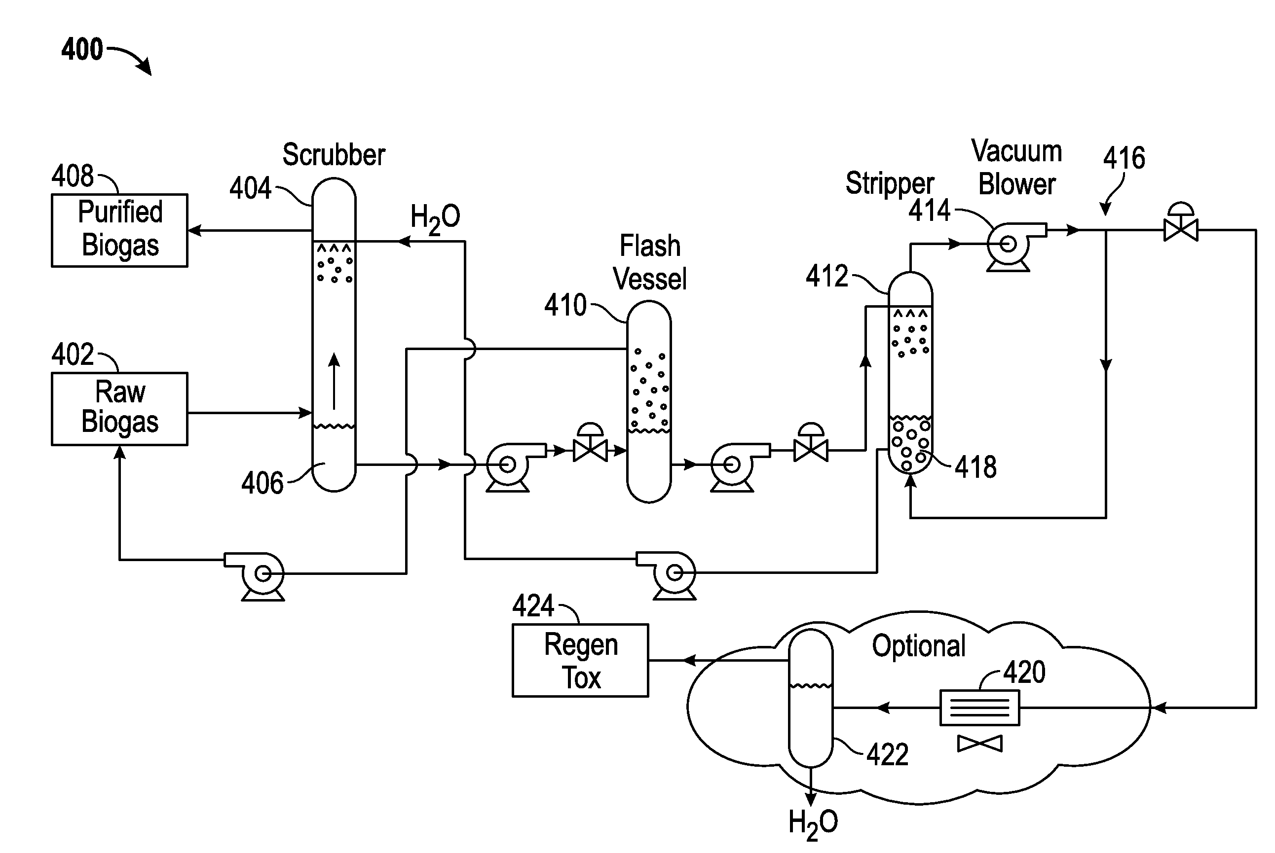
System for the treatment and purification of biogas with elimination of airflow from a scrubber system
a scrubber system and biogas technology, applied in the field of biogas treatment and purification systems, can solve the problems of inability to efficiently combust or oxidize the off-gas, inability to process the raw gas from landfills and digesters using a conventional biological h/sub>s removal system, and inability to meet the needs of metallurgy such as carbon and stainless steel, to achieve the effect of reducing the amount of absorbed gas
- Summary
- Abstract
- Description
- Claims
- Application Information
AI Technical Summary
Benefits of technology
Problems solved by technology
Method used
Image

Examples
Embodiment Construction
[0043]In the following paragraphs, the present invention will be described in detail by way of example with reference to the attached drawings. Throughout this description, the preferred embodiment and examples shown should be considered as exemplars, rather than as limitations on the present invention. As used herein, the “present invention” refers to any one of the embodiments of the invention described herein, and any equivalents. Furthermore, reference to various feature(s) of the “present invention” throughout this document does not mean that all claimed embodiments or methods must include the referenced feature(s). Additionally, various aspects of certain systems and methods for treatment of biogas described herein may also be found in co-pending and commonly assigned U.S. Utility patent application Ser. No. 13 / 557,004, the disclosure of which is hereby incorporated by reference in its entirety.
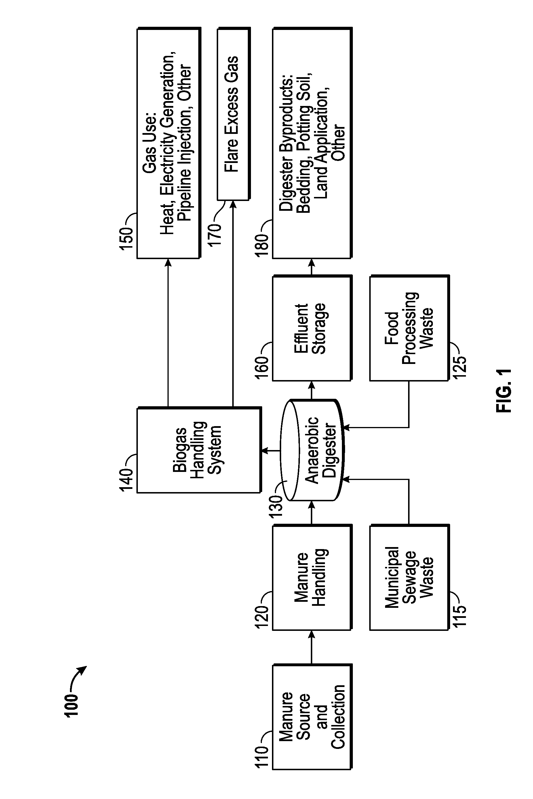
[0044]Biogas is a renewable energy composed primarily of methane resulting from the...
PUM
| Property | Measurement | Unit |
|---|---|---|
| flow rates | aaaaa | aaaaa |
| pressure | aaaaa | aaaaa |
| volatile | aaaaa | aaaaa |
Abstract
Description
Claims
Application Information