Microfluidics Delivery Systems

a technology of microfluidics and delivery systems, applied in the field of microfluidics, can solve the problems of inability to obtain high-purity materials using direct-write deposition, material purity, undesirable properties of deposited materials, etc., and achieve the effect of improving the flow of liquid

Active Publication Date: 2014-06-05
FEI CO
View PDF2 Cites 9 Cited by
  • Summary
  • Abstract
  • Description
  • Claims
  • Application Information

AI Technical Summary

Benefits of technology

[0013]Embodiments of the invention provide methods and apparatuses for dispensing a small amount of fluid. Some embodiments provide a method for controlling the flow of a liquid into an evacuated chamber. In some embodiments, a channel provides use of a nanocapillary having one or more slits in the end as a fluid dispenser. In some embodiments, slits in the tip of a nanodispenser provide improved flow of liquid from the nanodispenser.

Problems solved by technology

It is often difficult to obtain high purity materials using direct-write deposition, primarily due to the incorporation into the deposit of other components of the precursor molecules or the elements from the incident ion beam, such as gallium ions.
This lack of control of composition, material purity, or internal structure often leads to undesirable properties in the deposited material.
Charged particle beam-induced deposition has been limited by the availability of vapor phase precursors with requisite properties, that is, high residency time (stickiness) on the surface, lack of spontaneous decomposition, and decomposition in the presence of the beam to deposit the desired material and form a volatile byproduct.
When suitable deposition precursors do exist for a particular material, the deposition rates are often limited by gas depletion effects and other factors.
The precursor molecules typically cause a substantial increase in the pressure in the vacuum chamber, which can scatter the beam, and most of the precursor molecules are removed by the vacuum pump without reacting, thereby wasting the precursor, which is often a hazardous substance.

Method used


Image

  • Microfluidics Delivery Systems
  • Microfluidics Delivery Systems
  • Microfluidics Delivery Systems

Examples


Embodiment Construction

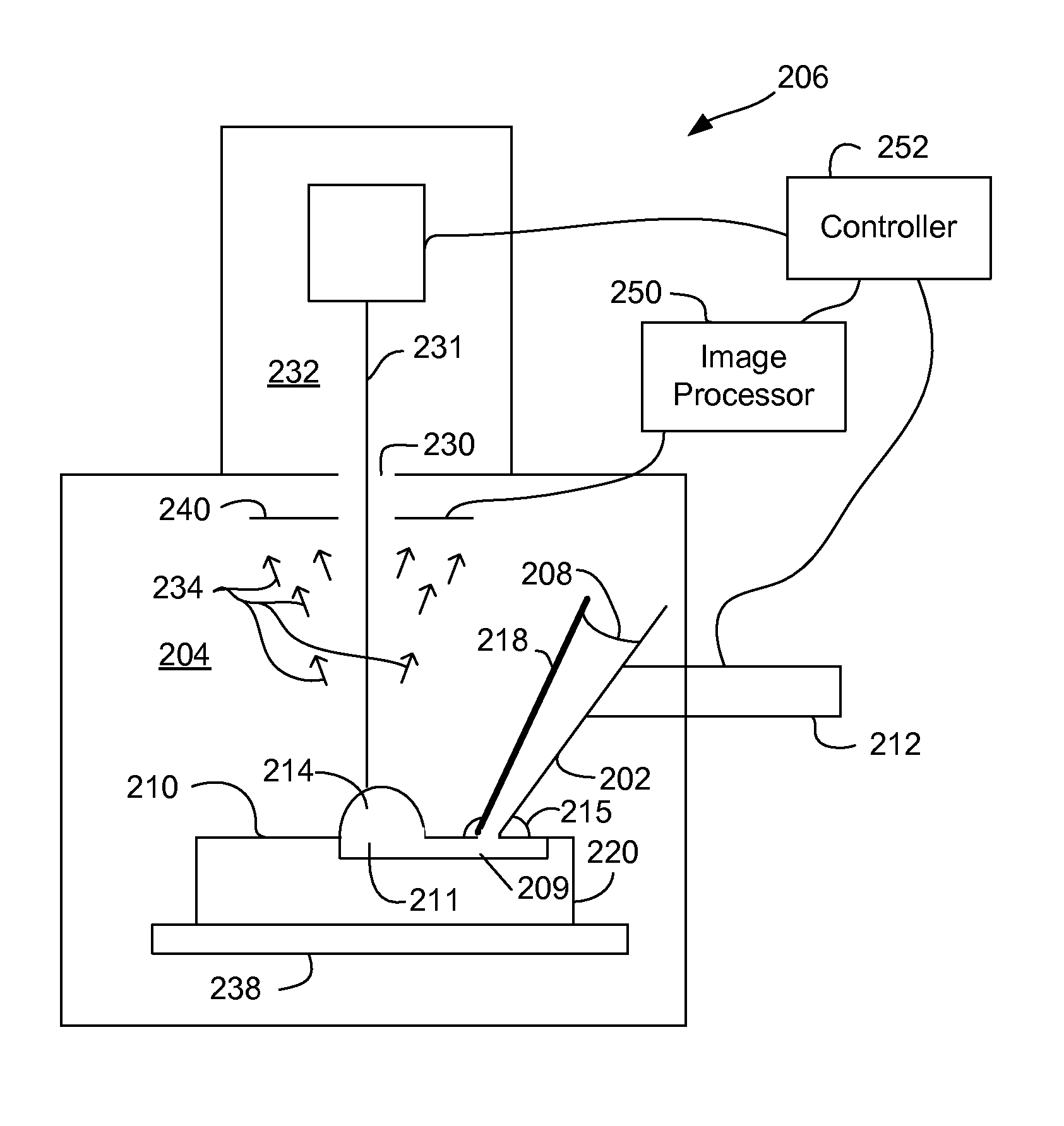
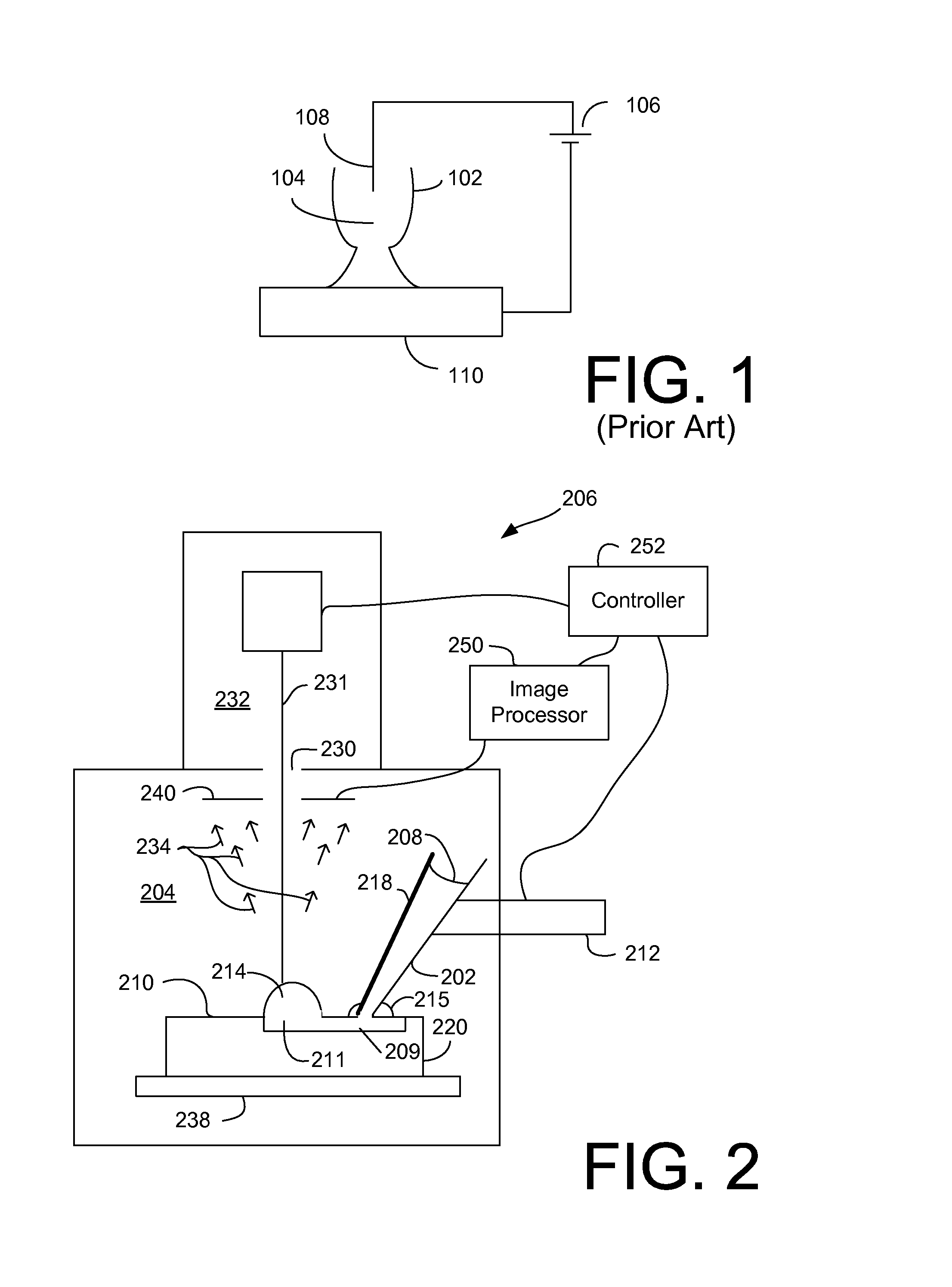
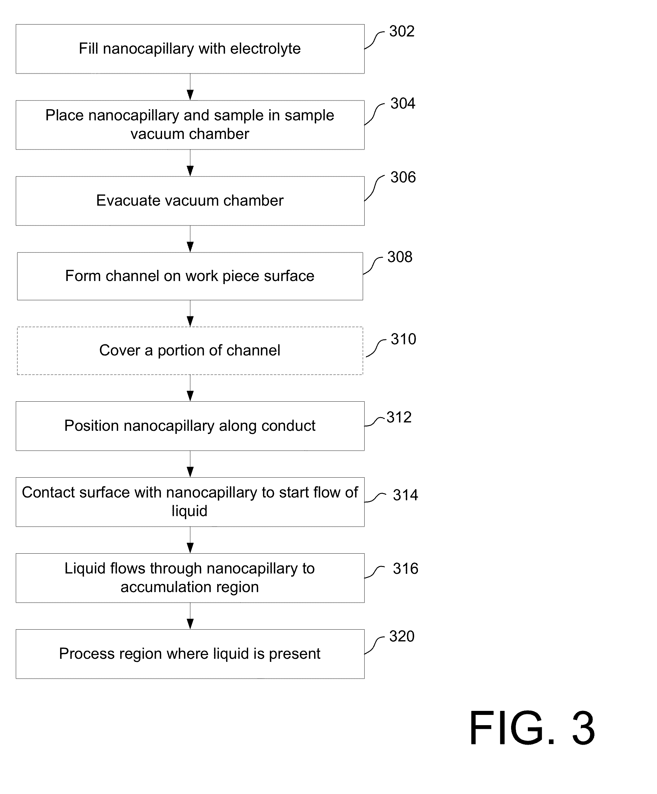
[0035]Embodiments of the invention supply a small amount of liquid onto a work piece surface for micro or nanoprocessing. Some embodiments can dispense a precise amount of liquid and deliver the liquid to a precise location on the work piece. Some embodiments are especially useful in a vacuum chamber, such as a vacuum chamber of a charged particle beam system. Some embodiments are also useful outside of a vacuum chamber.

[0036]A “nanodispenser,” as used herein, comprises a device that dispenses small quantities of liquid upon a substrate. Nanodispensers can comprise, for example, nanocapillaries, nanosyringes, nanopipettes, etc. A nanodispenser can move relative to the work piece dispensing liquid, or the nanodispenser can dispense from a fixed position.

[0037]The rate at which liquid is dispensed from the nanodispensers depends on the application. The apparent bubble size is a function of the dynamic equilibrium between evaporation of the fluid from the bubble into vacuum, and supply...


PUM

PropertyMeasurementUnit
diameteraaaaaaaaaa
diameteraaaaaaaaaa
inner diameteraaaaaaaaaa

Abstract

Methods of dispensing a small amount of liquid onto a work piece includes in some embodiments known providing a microscopic channel for the liquid to flow from the nanodispenser. In some embodiments, dispensing the liquid includes dispensing the liquid using a nanodispenser have at least one slit extending to the tip. Some methods include controlling the rate of evaporation or the rate of liquid flow to establish an equilibrium producing a bubble of a desired size.

Description

TECHNICAL FIELD OF THE INVENTION[0001]The present invention relates to the use of microfluidics for charged particle beam systems.BACKGROUND OF THE INVENTION[0002]Microscopic processing often requires a small quantity of a compound to be provided at a precise location on a work piece. For example, vapor phase precursor molecules directed to a region of a work piece dissociate in the presence of a focused beam, such as a charged particle beam or a laser beam, to deposit material or to etch a work piece in a precise pattern. Stains or markers applied to a region of interest on a work piece surface may increase the contrast of structures in a biological system for imaging with an electron or optical microscope. An electrolyte applied to the surface of the work piece may be used for local electrochemical deposition or etching of a material. Reactants may combine in a microscopic reactor on a work piece to produce a desired product or to test for the presence of a substance.[0003]Charged...

Claims


Application Information

Patent Timeline
Patent Type & Authority Applications(United States)
IPC IPC(8): B05D1/26C25F3/14C25D5/02
CPCB05D1/26C25F3/14C25D5/024G01N23/225Y10T137/0324
Inventor BOTMAN, AURELIEN PHILIPP JEAN MACLOURANDOLPH, STEVENUTLAUT, MARK W.
Owner FEI CO
Why Eureka
Try Eureka