Recyclable buffer for the hydrothermal hydrocatalytic treatment of biomass

a hydrocatalytic treatment and biomass technology, applied in the field of hydrocatalytic treatment of biomass, can solve the problems of difficult penetration of lignocellulose biomass structure with chemicals, difficult to break down the long chain polymer structure of cellulose into carbohydrates that can be used to produce fuel, etc., and achieve the effect of minimal loss of active metal and maintaining activity

Inactive Publication Date: 2014-06-19
SHELL OIL CO
View PDF9 Cites 67 Cited by
  • Summary
  • Abstract
  • Description
  • Claims
  • Application Information

AI Technical Summary

Benefits of technology

[0008]It was found desirable to carry out catalytic hydrogenation/hydrogenolysis/hydrodeoxygenation of the biomass with a catalysis

Problems solved by technology

However, production of fuel from cellulose poses a difficult technical problem.
Some of the factors for this difficulty are the physical density of lignocelluloses (like wood) that can make penetration of the biomass structure of lignocelluloses with chemicals difficult and the chemical complexity of lignocelluloses that lead to difficulty in breaking down the long chain polymeric structure of cellulose into carbohydrates that can be used to produce fuel.
Unfortunately, the progress in de

Method used


Image

  • Recyclable buffer for the hydrothermal hydrocatalytic treatment of biomass

Examples


example 1

Ammonia buffer

[0089]A 75-milliliter Parr5000 reactor was charged with 30.21 grams of 50 wt % glycerol in deionized water, 0.202 grams of ammonium carbonate buffer, and 0.304 grams of the catalyst (DC-2534, containing 1-10% cobalt oxide and molybdenum trioxide (up to 30 wt %) on alumina, and less than 2% nickel), obtained from Criterion Catalyst & Technologies L.P., and sulfided by the method described in US2010 / 0236988 Example 5.

[0090]The reactor was pressured to 53 bar with hydrogen and heated to 250° C. for 5 hours. A final pH of 5.6 was obtained, indicating effective buffering of acetic and other acids formed as a byproduct of reaction

[0091]Reactor product was analyzed by gas chromatography using a 60-m×0.32 mm ID DB-5 column of 1 μm thickness, with 50:1 split ratio, 2 ml / min helium flow, and column oven at 40° C. for 8 minutes, followed by ramp to 285° C. at 10° C. / min, and a hold time of 53.5 minutes. The injector temperature was set at 250° C., and the detector temperature was...

example 2

Distillation with Ammonia Buffer

[0092]The reactor contents from Example 1 were distilled in a short path still at atmospheric pressure, under a blanket of nitrogen. The distillation was continued at a bottoms temperature from 142.5 to 245° C., to yield 50.1% of the initial charge as an overhead product. The pH of the distillate averaged to 7.5, while a pH of 8.6 was obtained for the final distillate sample comprising 8% of the initial charge. The pH of the remaining bottoms fraction was 6.6.

[0093]This example demonstrates the ability to distill the ammonia buffer overhead as base, which can be recycled to neutralize acidity in a subsequent reaction cycle.

[0094]Example 3 and 4

Buffer recycle

[0095]Two 75-milliliter Parr5000 reactors were charged with 10 grams of deionized water as solvent, 0.25 grams of the DC-2534 catalyst from example 1, and 2.7 grams of southern pine mini-chips (39% moisture). 10 grams of combined overhead distillate from example 2 (pH 8.6) were added to the reactor...


PUM

PropertyMeasurementUnit
Temperatureaaaaaaaaaa

Abstract

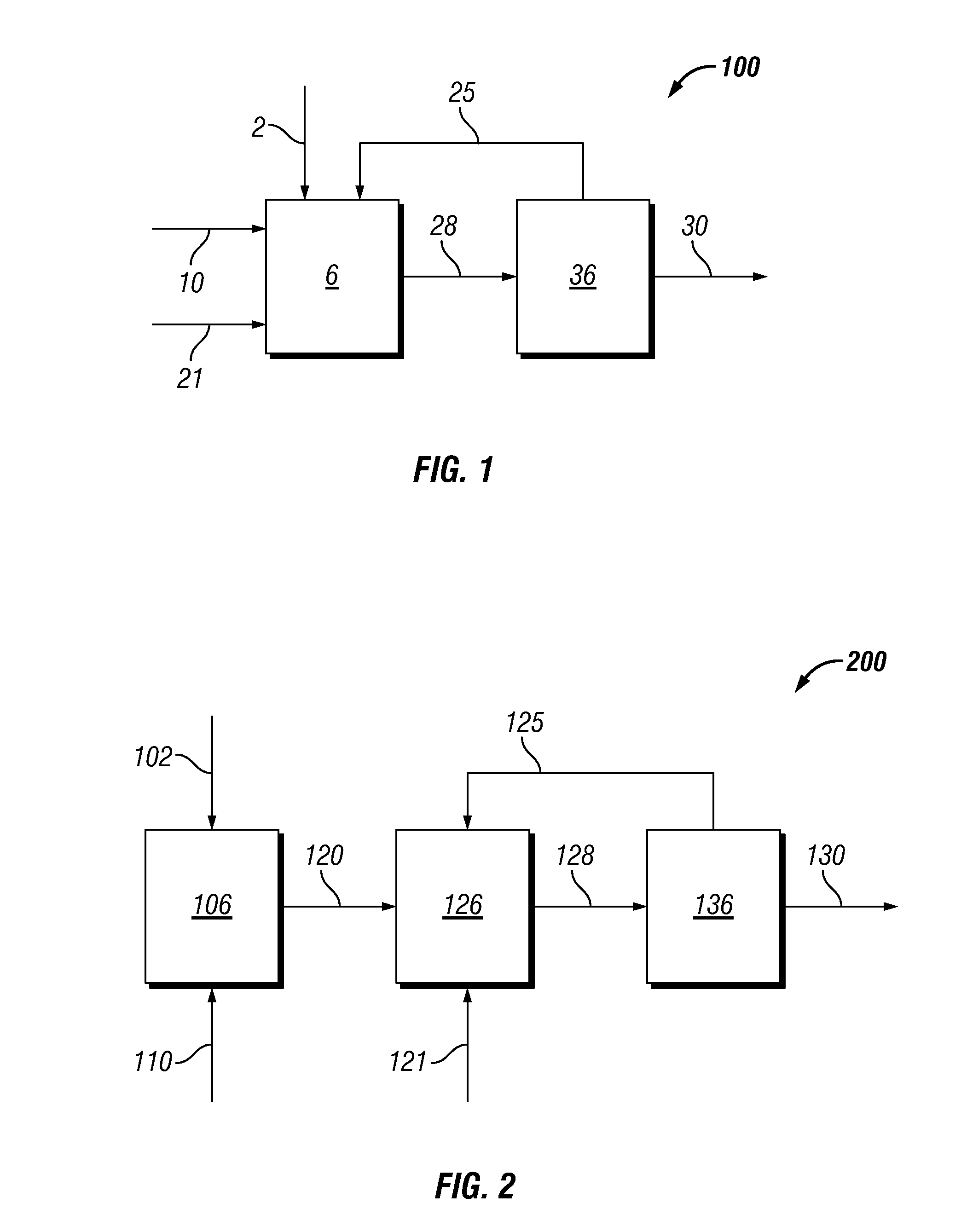
A method of hydrothermal hydrocatalytic treating biomass is provided. Lignocellulosic biomass solids is provided to a hydrothermal digestion unit in the presence of a digestive solvent, at least one of ammonia or a source of ammonia, and a supported hydrogenolysis catalyst containing (a) sulfur, (b) Mo or W, and (c) Co, Ni or mixture thereof, incorporated into a suitable support. The lignocellulosic biomass solids and digestive solvent are heated in the presence of hydrogen, supported hydrogenolysis catalyst and the at least one of ammonia or a source of ammonia forming a product solution containing plurality of oxygenated hydrocarbons and ammonia. At least a portion of ammonia is separated and recycled to the hydrothermal digestion unit.

Description

[0001]This non-provisional application claims the benefit of pending U.S. Provisional Patent Application Ser. No. 61 / 739,354, filed Dec. 19, 2012, the entire disclosure of which is hereby incorporated by reference.FIELD OF THE INVENTION[0002]The invention relates to the hydrothermal hydrocatalytic treatment of biomass in the production of higher hydrocarbons suitable for use in transportation fuels and industrial chemicals from biomass.BACKGROUND OF THE INVENTION[0003]A significant amount of attention has been placed on developing new technologies for providing energy from resources other than fossil fuels. Biomass is a resource that shows promise as a fossil fuel alternative. As opposed to fossil fuel, biomass is also renewable.[0004]Biomass may be useful as a source of renewable fuels. One type of biomass is plant biomass. Plant biomass is the most abundant source of carbohydrate in the world due to the lignocellulosic materials composing the cell walls in higher plants. Plant cel...

Claims


Application Information

Patent Timeline
IPC IPC(8): D21C3/00
CPCC07G1/00C10G1/065C10G3/46C10G3/50C10G3/56C10G2300/1014Y02P30/20Y02P20/582D21C3/006
Inventor POWELL, JOSEPH BROUNKOMPLIN, GLENN CHARLESSMEGAL, JOHN ANTHONYJOHNSON, KIMBERLY ANN
Owner SHELL OIL CO
Why Eureka
Try Eureka