Selectively Leached Cutter

a cutting element and selective technology, applied in the field of polycrystalline diamond cutting elements, can solve the problems of imposing a limit on the maximum useful operating temperature of the element, assembly is subjected to very high temperature and pressure, and pcd elements may be subject to thermal degradation, so as to achieve the effect of reducing the leaching depth

Inactive Publication Date: 2014-06-19
HALLIBURTON ENERGY SERVICES INC
View PDF2 Cites 28 Cited by
  • Summary
  • Abstract
  • Description
  • Claims
  • Application Information

AI Technical Summary

Benefits of technology

[0066]An embodiment of the present invention further comprises: determining an updated isotherm for the temperature experienced in the PCD body if leached according to the set leaching profile and under application of the operating temperature at the working portion, wherein the isotherm is indicative of the depth to which the temperature, will persist at which unleached portions of the PCD body will experience thermal degradation; and adjusting the leaching profile by identifying differences between the updated isotherm and the set leaching profile, and adjusting the set leaching profile to reduce the leached depth in portions of the leaching profile deeper than the isotherm, whilst eliminating regions where the isotherm indicates that thermal degradation is likely to occur.
[0068]In these or other embodiments of the invention, the steps of determining an updated isotherm and adjusting the leaching profile are iteratively repeated for the adjusted leaching profile in place of the set leaching profile to minimise the leaching depth throughout the leaching profile whilst eliminating regions where thermal degradation is likely to occur.
[0073]According to a seventh aspect of the present invention, there is provided a polycrystalline diamond (PCD) cutting element having distinct leached cutting areas at two or three or more separate locations provided offset from an axis of the cutting element so as to be rotationally displaced from one another around said axis such that, by adjusting the rotational orientation of the cutting element about the axis when fixing the cutting element to a cutting tool, each of the two or three or more cutting areas can independently be brought into a cutting position in which they perform cutting during use of the cutting tool.

Problems solved by technology

A common trait of PCD elements is the use of catalyzing materials during their formation, the residue from which often imposes a limit upon the maximum useful operating temperature of the element while in service.
However, modern PDCs typically utilize complex geometrical interfaces between the diamond table and the substrate as well as other physical design configurations to improve the impact strength.
The assembly is then subjected to very high temperature and pressure in a press.
Such PCD elements may be subject to thermal degradation due to differential thermal expansion between the interstitial cobalt binder-catalyzing material and the diamond matrix, beginning at temperatures of about 400 degrees C. Upon sufficient thermal expansion, the diamond-to-diamond bonding may be ruptured and cracks and chips may occur.
Due to the presence of the binder-catalyzing material, the diamond is caused to graphitize as temperature increases, typically limiting the operation temperature to about 750 degrees C.
Leaching the binder-catalyzing material may increase the temperature resistance of the diamond to about 1200 degrees C. However, the leaching process also has a tendency to remove the cemented carbide substrate.
In addition, where there is no integral substrate or other bondable surface, there are severe difficulties in mounting such material for use in operation.
This low diamond volume density enables a thorough leaching process, but the resulting furnished part is typically relatively weak in impact strength.
The resulting product typically has an abrupt transition between the preform and the barrier layer, causing problematic stress concentrations in service.
It is believed that the weakness of all these processes is the degradation of the diamond-to-diamond bonds in the polycrystalline diamond preform from the high temperature and pressure re-sintering process.
It is felt that this degradation generally further reduces the impact strength of the finished product to an unacceptably low level below that of the preform.
The process for making polycrystalline diamond with a silicon catalyzing material is quite similar to that described above, except that, at synthesis temperatures and pressures, most of the silicon is reacted to form silicon carbide, which is not an effective catalyzing material.
Again, there are mounting problems with this type of PCD element because there is no bondable surface.
However, the material is difficult to produce on a commercial scale since much higher pressures are required for sintering than is the case with conventional and thermally stable polycrystalline diamond.
Again, thermal degradation may still occur due to the residual binder-catalyzing material remaining in the interstices.
Again, because there is no integral substrate or other bondable surface, there are difficulties in mounting this material to a working surface.
Although these materials have very high diamond densities because they are so closely packed, there is no significant amount of diamond to diamond bonding between adjacent crystals, making them quite weak overall, and subject to fracture when high shear loads are applied.
The result is that although these coatings have very high diamond densities, they tend to be mechanically weak, causing very poor impact toughness and abrasion resistance when, used in highly loaded applications, such as when used as drill bit cutting elements.
Although this type of processing may improve the wear resistance of the diamond layer, the abrupt transition between the high-density diamond layer and the substrate make the diamond layer susceptible to wholesale fracture at the interface at very low strains, similar to the above described problems encountered with composite structures having barrier layers.
This again translates to very poor toughness and impact resistance in service.

Method used


Image

  • Selectively Leached Cutter
  • Selectively Leached Cutter
  • Selectively Leached Cutter

Examples


Embodiment Construction

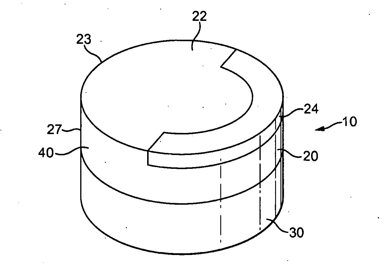
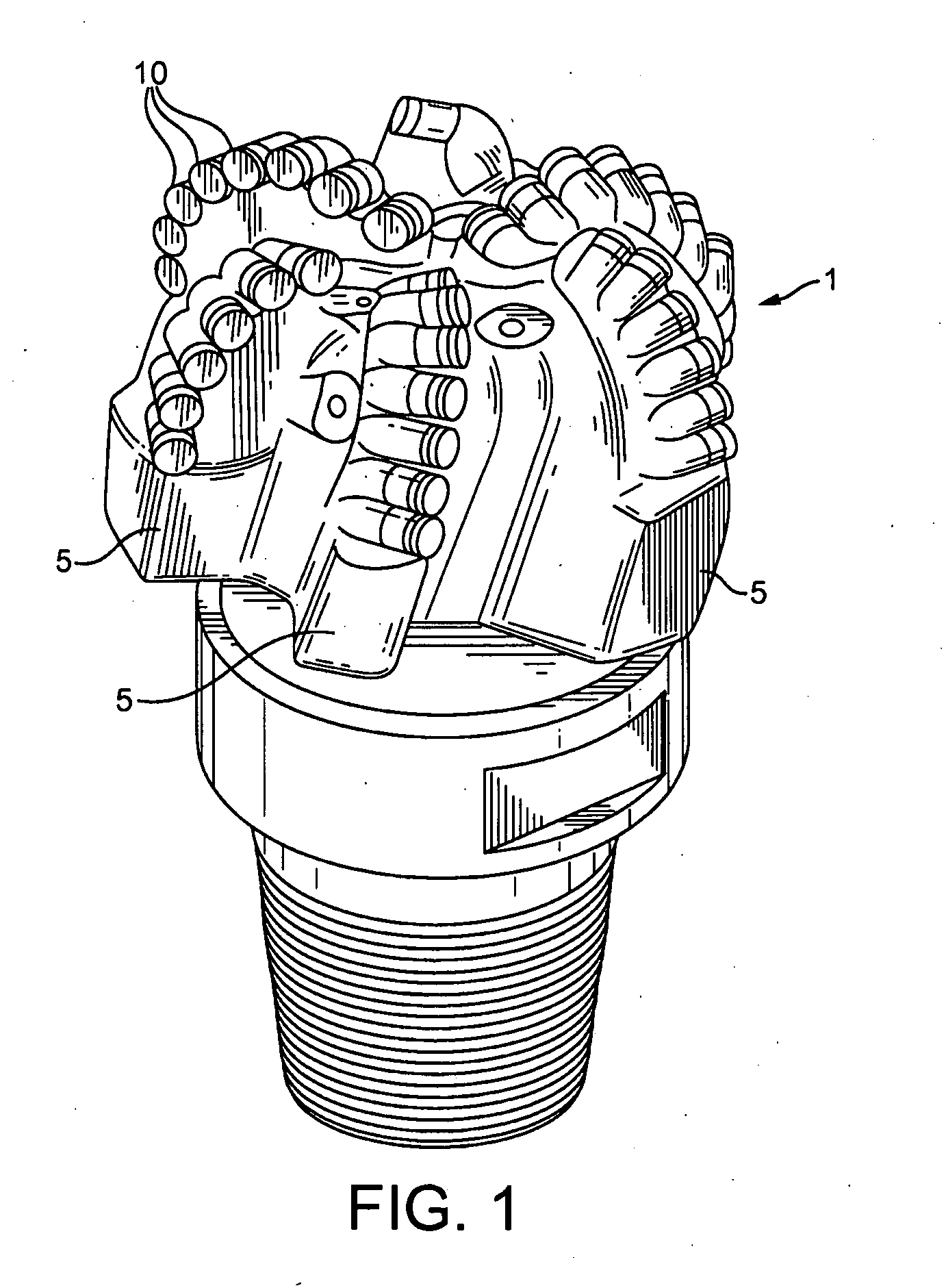
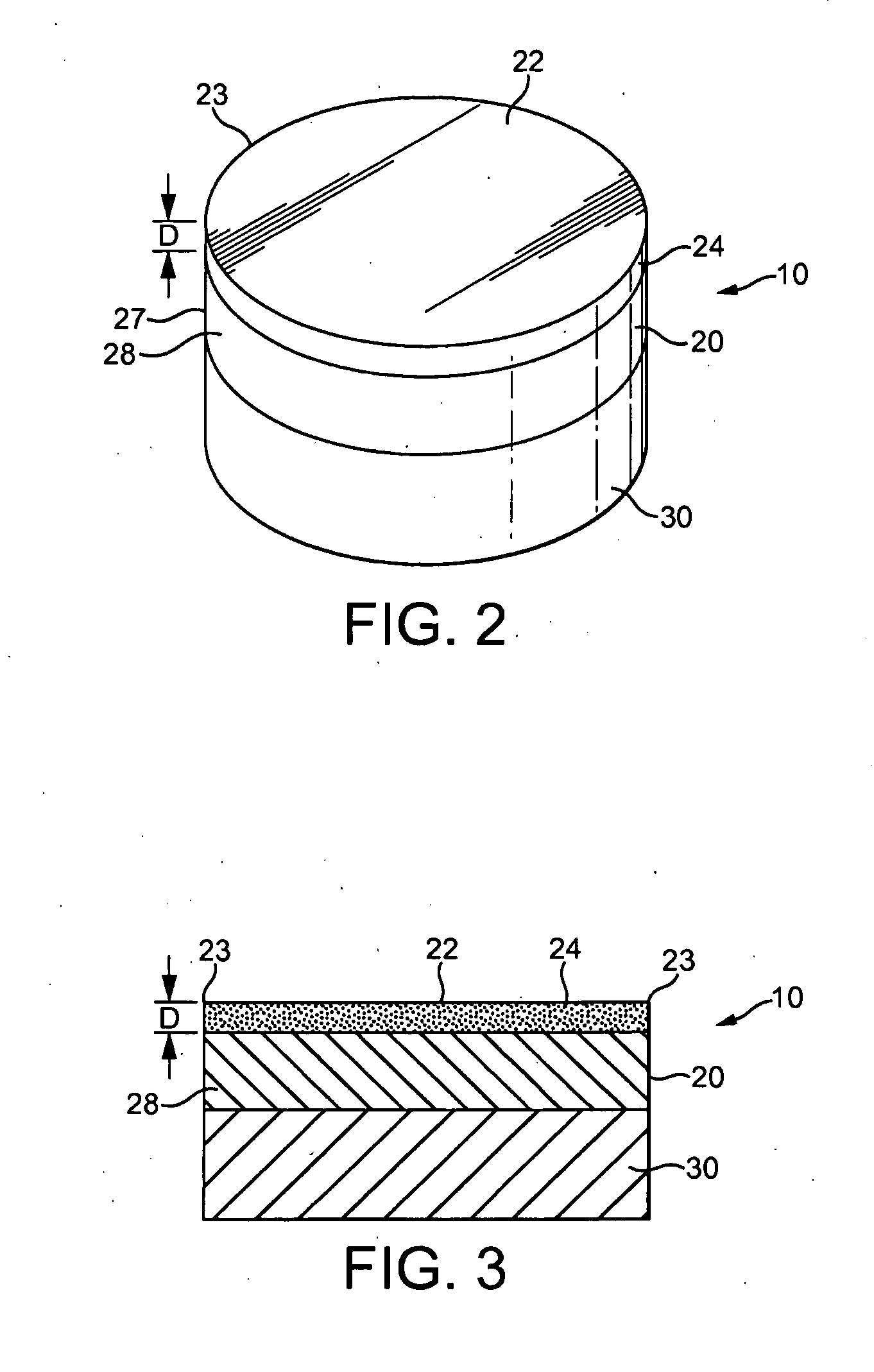
[0109]Before referring specifically to the drawings, some general characteristics of PCD elements and PCD cutting elements (also called polycrystalline diamond cutters, or PDCs) should be noted.

[0110]Polycrystalline diamond and polycrystalline diamond-like elements are collectively called PCD elements for the purposes of this specification. These elements are formed with a binder-catalyzing material in a high-temperature, high-pressure (HTHP) process. The PCD element has a plurality of partially bonded diamond or diamond-like crystals forming a continuous diamond matrix table or body. It is the binder-catalyzing material that allows the intercrystalline bonds to be formed between adjacent diamond crystals at the relatively low pressures and temperatures obtainable in a press suitable for commercial production.

[0111]The diamond matrix body may have a diamond volume density greater than 85%. During the process, interstices among the diamond crystals form into a continuous interstitial...


PUM

PropertyMeasurementUnit
depthaaaaaaaaaa
depthaaaaaaaaaa
depthaaaaaaaaaa

Abstract

A method of manufacturing a polycrystalline diamond (PCD) cutting element used as drill bit cutting elements (10) is disclosed. The method comprises leaching a PCD body formed from diamond particles (202) using a binder-catalyzing material so as to remove substantially all of the binder-catalyzing material from portions of a cutting surface of the PCD body. A portion (24) of the cutting surface is identified as a cutting area which, in use of the cutting element to cut material, is heated by the cutting action of the cutting element. Leaching of the PCD body includes performing a relatively deep leach in the portion of the cutting surface identified as the cutting area and performing a relatively shallow leach in at least the portion (26) of the cutting surface surrounding the identified cutting area.

Description

CROSS-REFERENCE TO RELATED APPLICATION[0001]This application claims the benefit of British Patent Application Serial No. 1106765.9, filed on Apr. 20, 2011, the entire disclosures of which are hereby incorporated by reference.FIELD OF THE INVENTION[0002]The present invention relates to polycrystalline diamond cutting elements, and to methods for leaching and methods for manufacturing the same.TECHNICAL BACKGROUND[0003]Polycrystalline diamond and polycrystalline diamond-like elements are known, for the purposes of this specification, as PCD elements. PCD elements are formed from carbon based materials with exceptionally short inter-atomic distances between neighbouring atoms. One type of diamond-like material similar to PCD is known as carbonitride (CN) described in U.S. Pat. No. 5,776,615. In general, PCD elements are formed from a mix of materials processed under high-temperature and high-pressure into a polycrystalline matrix of inter-bonded superhard carbon based crystals. A commo...

Claims


Application Information

Patent Timeline
Patent Type & Authority Applications(United States)
IPC IPC(8): E21B10/573B24D3/10
CPCB24D3/10E21B10/573B22F7/08B22F2005/001C22C1/00C22C19/07C22C26/00C22C29/08E21B10/567E21B10/5676E21B10/46
Inventor WHITTAKER, MALCOLM E.
Owner HALLIBURTON ENERGY SERVICES INC
Why Eureka
Try Eureka