On-chip thin film zernike phase plate and applications thereof

a thin film, phase plate technology, applied in the direction of material analysis using wave/particle radiation, instruments, nuclear engineering, etc., can solve the problems of significant loss of resolution, not precluding the major advantage of characterizing nano-structures of organic materials, and complicating image interpretation, so as to achieve effective release of charging results, prolong life, and stable performance

Inactive Publication Date: 2014-06-19
ACAD SINIC
View PDF5 Cites 25 Cited by
  • Summary
  • Abstract
  • Description
  • Claims
  • Application Information

AI Technical Summary

Benefits of technology

[0006]The present invention provides an on-chip thin film Zernike phase plate system, operated on a commercial TEM, which can effectively release the charging resulted from the phase plate, provide a steady performance, and realize the in-focus TEM phase imaging by routine operation of the TEM phase plates of the present invention. In the present invention, a chip fabricated and cut out from a wafer is combined with the conventional Zernike carbon phase plate, so the charging accumulated in the phase plate can be effectively released. Therefore, the phase plate of the present invention has a prolonged life and can be routinely used. Such a reliable system allows us to recognize and verify an unexpected nano-phase in polymer solar cell samples of in-device thickness. Moreover, we are able to observe fine structures of bio-specimens without staining using this stable TEM phase imaging technique.

Problems solved by technology

Transmission electron microscopy (TEM) has long been used for characterizing nano / micro-structures in materials, while its application on organic materials has been limited because the contrast of TEM images for organic specimens is usually poor since they are constituted with light elements, i.e. C, O, and N. The defocus technique is well known for enhancing contrast of TEM images, while it is a tricky technique for not only does it result in a significant loss of resolution, but it also causes some artifacts, consequently complicating the interpretation of the images.
Such a drawback, however, does not preclude its major advantage in characterizing nano-structures of organic materials which are too vague under conventional TEM.
Although Zernike phase plates have been successfully used to reveal the structure of ice-embedded biomolecules,18 a more reliable phase plate technique that allows phase contrast images to be taken reliably and repeatedly is still in need, since the performance of TEM phase plates deteriorates too quickly.7,13,16 One of the major causes for the unstable performance of a TEM phase plate is the charging effect.13,16 When a physical phase plate is present in the pathway of the electron beam, the build up of charged particles in some local sites would result in instability and distortion of the image formed.
Such a notorious charging effect resulting from phase plates has been known for some time, and is still considered an obstacle for TEM phase plate technology to be put into routine use until very recently.13,16 Practically, the investigation of nanostructures of organic materials with phase plates can hardly be realized without a reliable and routinely achievable method for taking in-focus phase TEM images.

Method used


Image

  • On-chip thin film zernike phase plate and applications thereof
  • On-chip thin film zernike phase plate and applications thereof
  • On-chip thin film zernike phase plate and applications thereof

Examples


example 1

TEM Image Drifting of the Phase Plates with and without Complete Conductive Layer Coating

[0060]A standard TEM specimen with Au nanoparticles (particle size <5 nm) was used to study the drifting pattern of TEM imaging. The standard specimen of Au was used to avoid the image drifting caused by the sample charging itself. It was found that when the phase plate chip was not loaded, the TEM image drifted towards the same direction with a drifting rate of ˜2 nm / min, and this is the mechanical drifting of the TEM system itself. Such a drifting rate is within the acceptable mechanical drifting range of the TEM system.

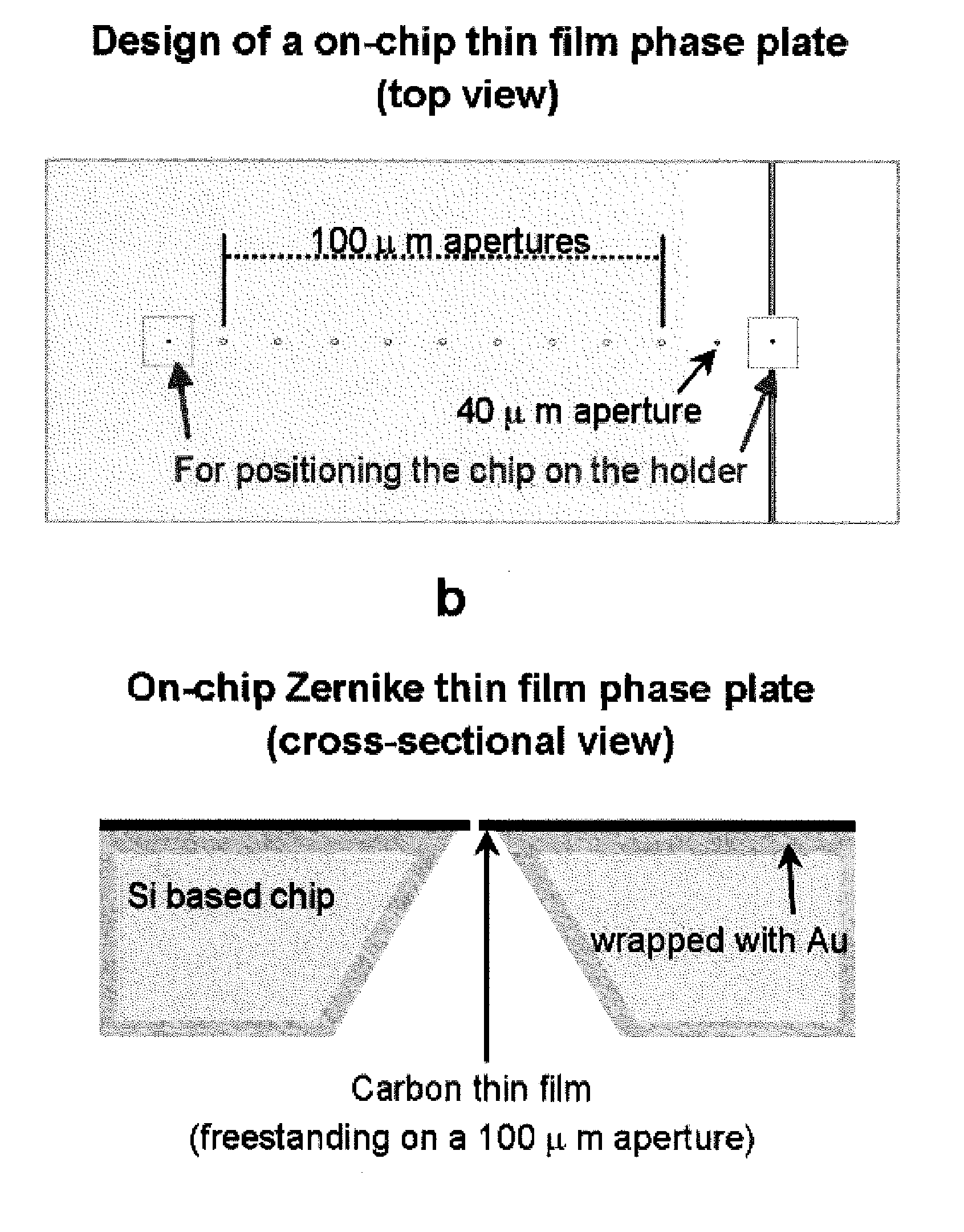
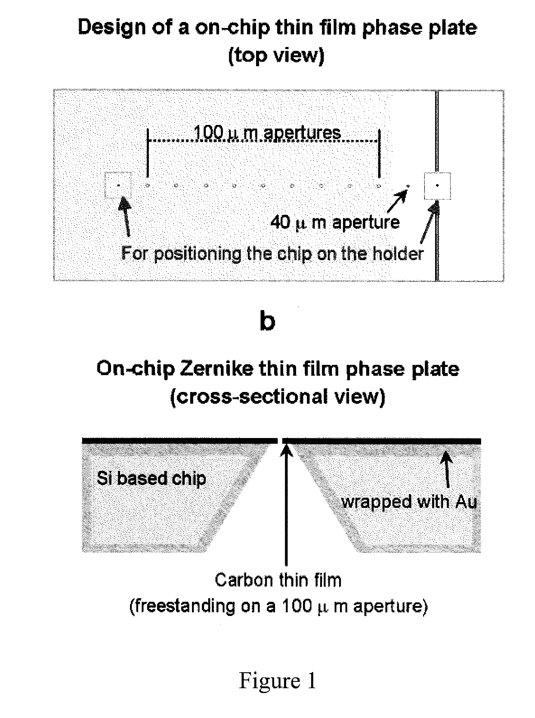
[0061]With the on-chip phase plate of the present invention in position, the imaging drifting rate and pattern were the same as those observed by the TEM system without the phase plate. However, the image drifting pattern is rather different if the substrate was poorly fabricated, in which the substrate was only coated with a top layer of Au instead of a 3-dimensional Au coatin...

example 2

Observation of Organic Material

[0064]With the on-chip thin film Zernike phase plate of the present invention, many organic devices, including OLED and polymer solar cell specimens, can be observed by TEM. FIG. 6(a) shows an in-focus TEM phase image of a photoactive layer of P3HT / PCBM (1:1) blend, which is taken by using the phase plate of the present invention; and FIG. 6(b) shows an in-focus TEM phase image of the same specimen, which is taken without using the phase plate of the present invention. The TEM specimen used in FIG. 6 has a thickness of ˜160 nm, and was prepared in the same way as a polymer layer fabricated in a solar cell device. The photoactive layer retrieved from a bulk heterojunction polymer solar cell device also can be used. In FIGS. 6(a), some spaghetti-like features are found, which are invisible in the in-focus TEM image without using a phase plate (see FIG. 6(b)). It is generally believed that P3HT causes the spaghetti-like phase. Conventionally, the TEM phot...

example 3

Observation of Biological Material

[0069]Besides characterizing organic devices, the TEM system of the present invention also has great potential in applications in biological fields. With its stable performance, imaging fine structures of biological samples without going through complicated sample preparation process, such as staining, becomes possible. FIG. 8(a) shows the in-focus TEM image of an unstained Escherichia coli (E. coli) specimen, which was obtained by using the on-chip phase plate of the present invention. For comparison, the same unstained E. coli specimen was observed using the same TEM imaging conditions but without adopting the phase plate of the present invention. The resulting image is shown in FIG. 8(b). The pili surrounding the cell envelope can be clearly seen in the phase image (FIG. 8(a)), but they cannot be identified in FIG. 8(b). The image contrast of the cell envelope itself is also enhanced in the phase image. The FFT images of FIGS. 8(a) and 8(b) are s...


PUM


Abstract

The present invention provides an on-chip thin film phase plate for a releasing charging, comprising a chip substrate having one or more apertures; and a thin film layer attached to the top surface of the chip substrate. The present invention also provides a method for observing organic material by TEM, which uses the above-mentioned on-chip thin film phase plate in a TEM system.

Description

BACKGROUND OF THE INVENTION[0001]1. Field of the Invention[0002]The present invention relates to an on-chip thin film Zernike phase plate for releasing charging, and applications thereof.[0003]2. Description of the Related Art[0004]Organic devices, such as polymer solar cells and organic light-emitted diodes (OLED), have attracted considerable attention in recent years. The efficiencies of these organic devices greatly depend on their nanoscale structures. For example, the nanoscale morphology affects the charge transport in the donor / acceptor blend, and hence influences the power conversion efficiency of a bulk heterojunction polymer solar cell.1-5 Characterizing nano-structures in organic devices thus has a critical importance in optimizing their performance. Transmission electron microscopy (TEM) has long been used for characterizing nano / micro-structures in materials, while its application on organic materials has been limited because the contrast of TEM images for organic speci...

Claims


Application Information

Patent Timeline
Patent Type & Authority Applications(United States)
IPC IPC(8): H01J37/26
CPCH01J37/295H01J2237/2614H01J37/26Y10S977/881
Inventor SHIUE, YUNN-SHINKUO, PAI-CHIACHEN, CHIH-TINGWANG, YUH-LINHSIEH, YONG-FEN
Owner ACAD SINIC
Why Eureka
Try Eureka