Methods and Apparatus Pertaining to Picosecond Pulsed Fiber Based Lasers

a fiber-based laser and pulsed technology, applied in the field of pulsed lasers, can solve the problems of fs pulses, considerably more difficult production, haz and damage in the heat affected zone, etc., and achieve the effects of low compression ratio, low spectral dispersion, and high spectral dispersion for compression

Active Publication Date: 2014-06-19
NKT PHOTONICS
View PDF8 Cites 18 Cited by
  • Summary
  • Abstract
  • Description
  • Claims
  • Application Information

AI Technical Summary

Benefits of technology

[0010]The present disclosure teaches, in certain practices, methods and apparatus pertaining to a pulsed fiber laser that uses a relatively high spectral dispersion for compression in combination with a relatively low compression ratio. Systems known in the art, such as conventional fs CPA architectures, teach that an opposite approach is advantageous, namely, relatively low spectral dispersion and relatively high compression ratio. Furthermore, in the ps regime, a ps pulse can often simply be directly produced, such as by fiber delivered pulsed seed laser (FDPSL), or other seed laser, and amplified by a fiber ...

Problems solved by technology

However, the pulses can be longer than desired, and result in more energy than necessary being delivered to a work piece, which can cause an undesirable “heat affected zone” (HAZ) and damage.
Fs pulses, however, can be considerably more difficult to produce and can require considerably more complex technology.
For example, amplifying such fs pulses directly can induce undesirable nonlinear effects, particularly in a fiber amplifier where the peak power is high due to the short time duration of the pulse and where the optical intensity, which triggers the nonlinear effects, is also high due to the relatively small cross sectional area of the typical o...

Method used


Image

  • Methods and Apparatus Pertaining to Picosecond Pulsed Fiber Based Lasers
  • Methods and Apparatus Pertaining to Picosecond Pulsed Fiber Based Lasers
  • Methods and Apparatus Pertaining to Picosecond Pulsed Fiber Based Lasers

Examples


Embodiment Construction

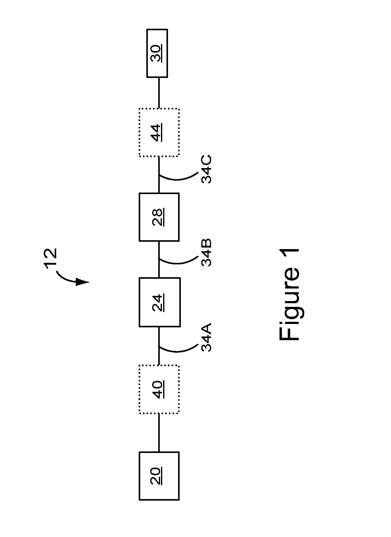
[0068]FIG. 1 schematically illustrates one embodiment according to the present disclosure of a pulsed fiber laser apparatus 12 for outputting picosecond (“ps”) laser pulses. The pulsed fiber laser apparatus 12 can comprise a pulsed seed laser 20, at least one optical fiber amplifier 24 in optical communication with the pulsed seed laser 20, a pulse compressor apparatus 28 in optical communication with the at least one optical fiber amplifier 24, and an optical output 30 in optical communication with the pulse compressor apparatus 28. Optical path 34A provides optical communication between the pulsed seed laser 20 and the least one optical fiber amplifier 24, which communicates with the pulse compressor apparatus 28 via optical path 34B. Optical path 34C provides optical communication between the pulse compressor apparatus 28 and the optical output 30. The at least one optical fiber amplifier 24 is considered optically “downstream” of the pulsed seed laser 20, the pulse compressor ap...


PUM

PropertyMeasurementUnit
Fractionaaaaaaaaaa
Fractionaaaaaaaaaa
Timeaaaaaaaaaa

Abstract

A pulsed fiber laser apparatus for outputting picosecond laser pulses can comprise a fiber delivered pulsed seed laser for providing picosecond optical seed pulses, and at least one optical fiber amplifier in optical communication with the fiber delivered pulsed seed laser. The optical fiber amplifier can comprise a gain optical fiber that receives and optically amplifies picosecond optical pulses by operating in a nonlinear regime wherein the picosecond optical pulses can be spectrally broadened by a factor of at least 8 during amplification thereof. The apparatus can further comprise a pulse compressor apparatus in optical communication with the optical fiber amplifier for providing compressed picosecond optical pulses. The pulse compressor apparatus can provide a dispersion of at least 50 ps/nm and can provide a compression ratio of the time duration of the picoseconds optical pulses received by the pulse compressor apparatus to the time duration of the compressed picosecond optical pulses of no greater than about 50.

Description

CROSS-REFERENCE TO RELATED APPLICATIONS[0001]The present application is continuation of International Patent Application No. PCT / US2012 / 052176, bearing an International Filing Date of 24 Aug. 2012, which in turn claims priority to U.S. Provisional Patent Application No. 61 / 527,042, accorded a filing date of 14 Sep. 2011, and to U.S. Provisional Patent Application No. 61 / 644,424, accorded a filing date of 8 May 2012. Each of the foregoing applications is incorporated by reference herein.FIELD OF THE DISCLOSURE[0002]The present disclosure relates to picosecond pulsed lasers, such as, for example, picosecond pulsed lasers that use optical fiber, as well as systems and methods for making and using such lasers.BACKGROUND OF THE DISCLOSURE[0003]Lasers based on optical fiber, whether in whole or in part, can provide more flexible, rugged and relatively simple sources of optical energy. For example, an optical fiber laser can have a smaller footprint, or can be more efficient, or can requir...

Claims


Application Information

Patent Timeline
IPC IPC(8): H01S3/00H01S3/08
CPCH01S3/0057B23K26/0624B23K26/36G02B27/283H01S3/005H01S3/0078H01S3/067H01S3/06725H01S3/06745H01S3/0675H01S3/06754H01S3/08013H01S3/094003H01S3/094007H01S3/094011H01S3/09415H01S3/1118H01S3/1618H01S3/2308
Inventor CLOWES, JOHN REDVERSALMEIDA, PAULOGRUDININ, ANATOLY BORISOVICHDUPRIEZ, PASCALCODEMARD, CHRISTOPHE
Owner NKT PHOTONICS
Why Eureka
Try Eureka