

Evaporation source
Active Publication Date: 2014-06-26
OERLIKON SURFACE SOLUTIONS AG PFAFFIKON
View PDF4 Cites 2 Cited by
- Summary
- Abstract
- Description
- Claims
- Application Information
AI Technical Summary
Benefits of technology
The present invention ensures efficient cooling of the cylindrical evaporation source by absorbing and transporting off heat at the site of input. This prevents excessive temperatures and damage to components inside the evaporation source such as a magnet system. The cooling takes up minimal space and does not require complex and expensive corrosion protection. A common fixing plate fixes the carrier body to the base body, and an expansion element compensates for differences in thermal expansion between components to prevent mechanical strains. These measures improve cooling efficiency.
Problems solved by technology
This high current density causes a lightning fast evaporation of the starting material.
A disadvantage of the coating plant and of the process in accordance with WO 90 / 02216 is inter alia that a uniform quality of the coatings is in particular not ensured.
The quality of the applied layers thus varies as the consumption of the cathodes increases if the method parameters are not tracked in a complex and / or expensive manner.
This is as known inter alia due to the fact that the rectangular cathodes are consumed in a non-uniform manner so that, with the same process parameters, the quality of the coating vapor becomes increasingly worse as the erosion of the cathodes increases because e.g. disturbing droplets form to an increasing degree in the arc evaporation, which has a negative effect on the layers.
To keep these negative effects within limits, the cathodes have to be replaced prematurely, which is correspondingly expensive and complicated.
A further disadvantage in addition to the irregular erosion of the cathodes is that a control of the arc on the cathode is very difficult and complicated, if possible at all.
A problem of cylindrical cathodes which has not yet been really satisfactorily solved is, however, their cooling.
A substantial disadvantage of such solutions is that the cooling takes up a significant space in the interior of the evaporation source which is then not available for further necessary installations such as for magnet systems which the skilled person would often advantageously like to accommodate in the interior of the evaporation source.
It was in addition shown that the conducting away of the heat is frequently not sufficiently efficient in such cooling systems, the installations are complicated and thus require frequent maintenance, which all in all naturally also drives up costs.
Method used
View moreImage
Smart ImageViewing Examples

Examples
second embodiment
[0041]FIG. 2 a second embodiment with an expansion element at the fixing plate;
third embodiment
[0042]FIG. 3a a third embodiment with a linear coolant supply; and
[0043]FIG. 3b an embodiment in accordance with FIG. 3a with an annular supply.
Login to View More PUM
| Property | Measurement | Unit |
|---|---|---|
| Magnetic field | aaaaa | aaaaa |
| Strength | aaaaa | aaaaa |
| Thermal expansion coefficient | aaaaa | aaaaa |
Abstract
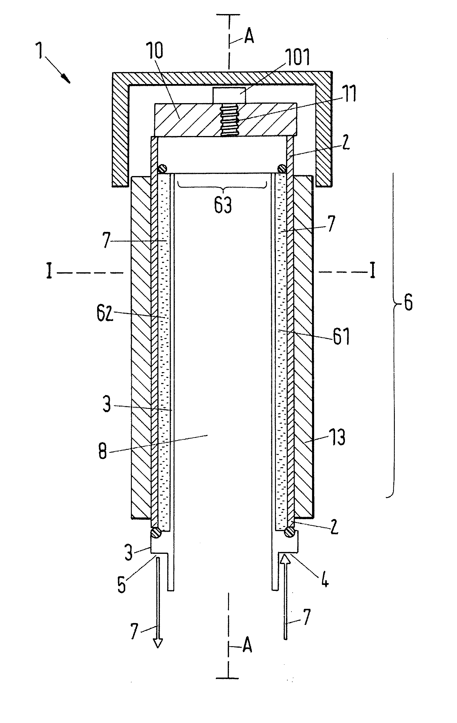
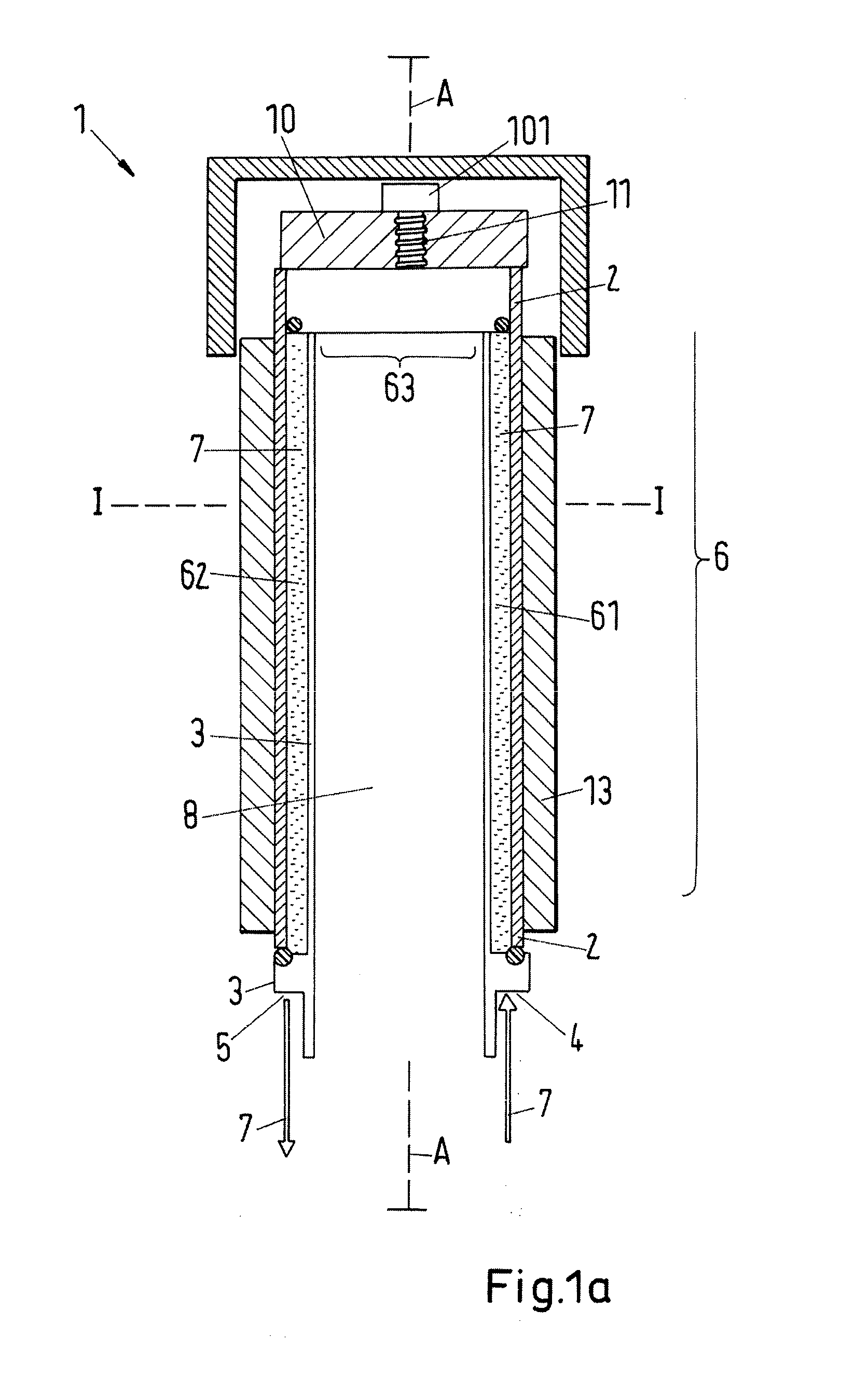
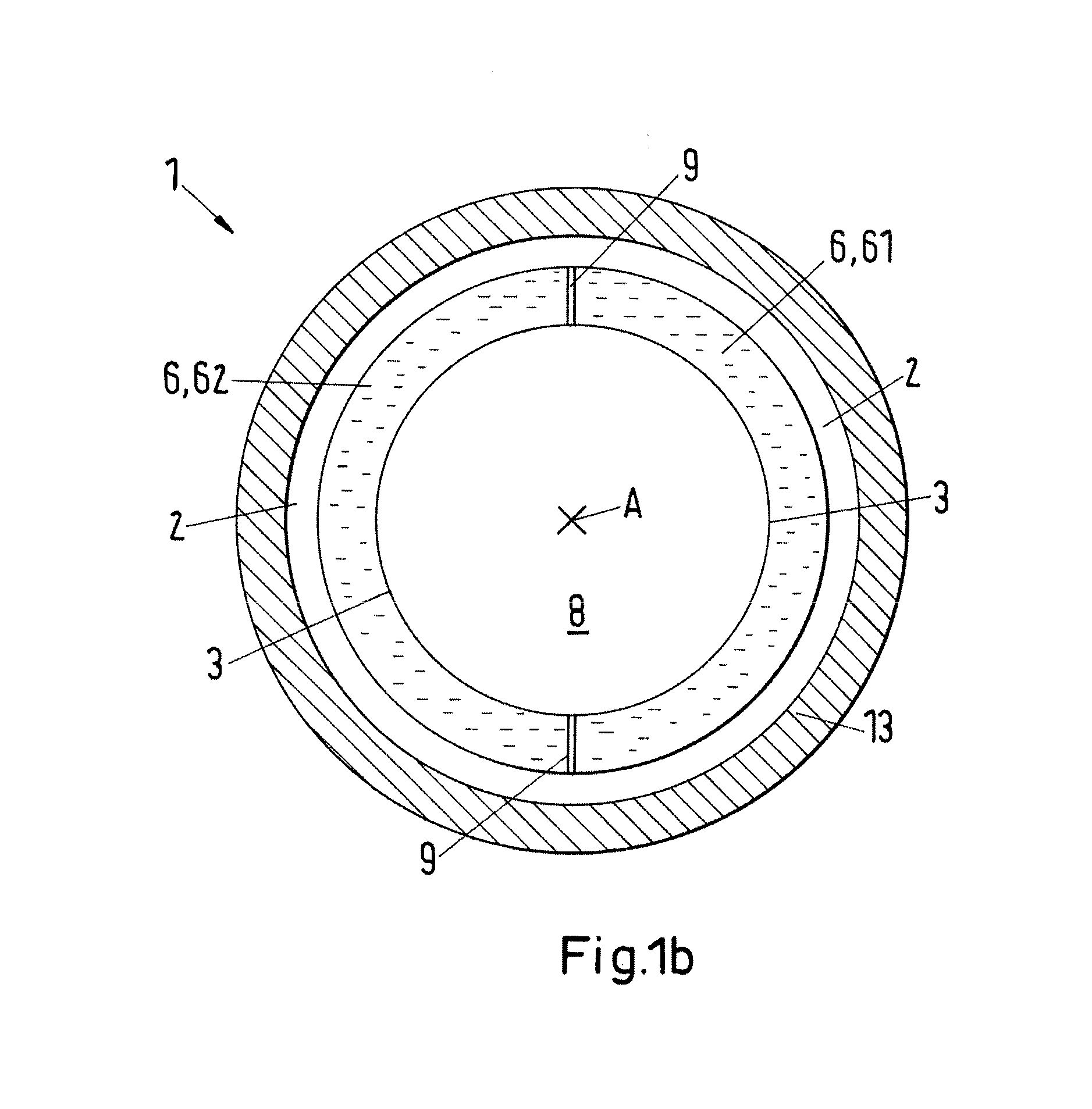
Evaporation source, in particular for use in a sputtering process or in a vacuum arc evaporation process, preferably a cathode vacuum arc evaporation process. The evaporation source includes an inner base body which is arranged in an outer carrier body and which is arranged with respect to the outer carrier body such that a cooling space in flow communication with an inlet and an outlet is formed between the base body and the carrier body. In accordance with the invention, the cooling space includes an inflow space and an outflow space, and the inflow space is in flow communication with the outflow space via an overflow connection for the cooling of the evaporation source such that a cooling fluid can be conveyed from the inlet via the inflow space the overflow connection and the outflow space to the outlet.
Description
CROSS-REFERENCE TO RELATED APPLICATIONS[0001]The present application is based on European Patent Application No. EP 1 219 8948.7 filed Dec. 21, 2012, the disclosure of which is expressly incorporated by reference herein in its entirety.BACKGROUND OF THE INVENTION[0002]1. Field of the Invention[0003]The invention relates to an evaporation source, in particular for use in a sputtering process or in a vacuum evaporation process, preferably a cathode vacuum evaporation process, in accordance with the preamble of independent claim 1.[0004]2. Discussion of Background Information[0005]A whole series of different chemical, mechanical and physical techniques are known from the prior art for the application of layers or layer systems on the most varied substrates, each of which techniques are valid and have corresponding advantages and disadvantages in dependence on the demand and on the area of use.[0006]Processes are in particular common for the application of comparatively thin layers or f...
Claims
Login to View More Application Information
Patent Timeline
 IPC IPC(8): H01J37/34H01J37/32
CPCC23C14/243C23C14/325C23C14/3407H01J37/3497H01J37/32055H01J37/3423H01J37/3435H01J37/32614H01J37/3414
InventorVETTER, JOERGESSER, STEFANMUELLER, JUERGENERKENS, GEORG
OwnerOERLIKON SURFACE SOLUTIONS AG PFAFFIKON