
Electrophotographic photoreceptor

a photoreceptor and electron-transporting technology, applied in the field of electron-transporting photoreceptors, can solve the problems of insufficient hole blocking properties, inability to achieve sufficient hole blocking properties, and inability to suppress positive holes in the photosensitive layer from the conductive support, etc., to achieve enhanced electron-transporting properties, suppress image defects such as black spots and fog, and enhance electron-transporting properties

Inactive Publication Date: 2014-06-26
KONICA MINOLTA INC
View PDF5 Cites 12 Cited by
  • Summary
  • Abstract
  • Description
  • Claims
  • Application Information

AI Technical Summary

Benefits of technology

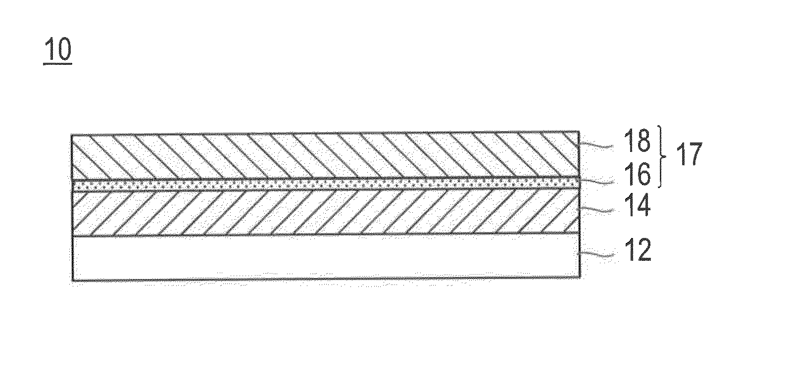
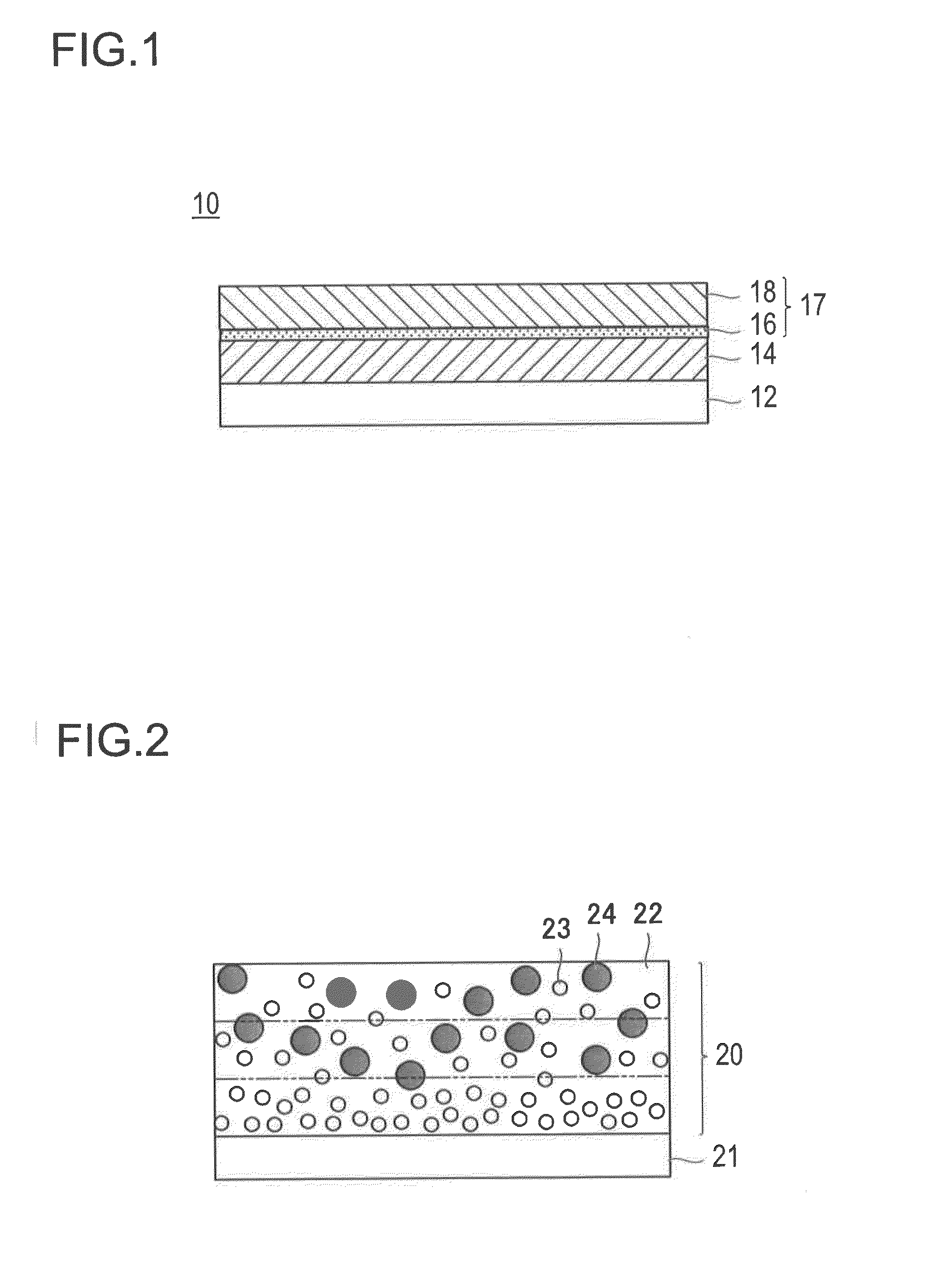
The patent describes a method for improving the performance of a photoreceptor by using two layers of metal oxide particles in an intermediate layer. The first layer of metal oxide particles acts to block irregular electrons and prevent image defects, while the second layer enhances electron-transporting properties to suppress image unevenness. By combining the functions of these two layers, the method effectively suppresses image defects and density unevenness in the resulting image. The method can be evaluated using a film simulation and surface potential measurements. The patent also mentions that particles with different surface treatments and particle sizes can be used for the metal oxide particles.

Problems solved by technology

However, when the electron-transporting properties are merely enhanced, the injection of the positive holes into the photosensitive layer from the conductive support cannot be satisfactorily suppressed.
Namely, enough hole blocking properties cannot be obtained.
When a highly sensitive charge generating material is used as a charge generating material contained in the charge generating layer, leakage of carriers generated by thermal excitation occurs and thereby partially reduces a surface potential of the electrophotographic photoreceptor, and there is a problem that image defects such as black spots and fog occur.
In particular, when the highly sensitive charge generating material is used in the charge generating layer, injection of irregular electrons cannot be satisfactorily suppressed, and it was found that the image defects such as black spots and fog easily occurred.

Method used


Image

  • Electrophotographic photoreceptor
  • Electrophotographic photoreceptor
  • Electrophotographic photoreceptor

Examples


example 1

Photoreceptor 1

[0177]“Photoreceptor 1” having a laminate structure obtained by forming successively an intermediate layer, a charge generating layer, and a charge transport layer on a conductive support was produced by the following procedure.

[0178]

[0179]A tube made of aluminum alloy of a length of 362 mm was attached to an NC lathe and subjected to cutting processing so that the outer diameter was 59.95 mm and Rzjis of the surface was 1.2 μm by a sintered diamond bite.

[0180]

[0181](Formation of Intermediate Layer)

[0182]100 parts by mass of the following polyamide resin (N-1) as a binder resin was added to 1850 parts by mass of a mixed solvent of ethanol / n-propyl alcohol / tetrahydrofuran (volume ratio: 50 / 20 / 30) and stirred and mixed at 20° C. 130 parts by mass of the surface-treated metal oxide particles 6 as the first metal oxide particles and 150 parts by mass of the surface-treated metal oxide particles 1 as the second metal oxide particles were added to the solution and dispersed...

examples 2 to 7

Photoreceptors 2 to 7

[0200]

[0201]An electrophotographic photoreceptor was produced in the same manner as Example 1, except that the surface-treated metal oxide particles contained in the intermediate layer of the photoreceptor 1 were changed as in the following Table 2-1.

example 8

Photoreceptor 8

[0202]

[0203]The photoreceptor 8 was produced in the same manner as the Example 2, except that the coating liquid for charge generating layer in the photoreceptor 2 was changed as follows.

[0204](Coating Liquid for Charge Generating Layer)

[0205]The following components were mixed and dispersed for 15 hours using a sand mill disperser, and, thus, to prepare the coating liquid for charge generating layer. The coating liquid was coated on an intermediate layer by dip coating, and a “charge generating layer” having a dried film thickness of 0.5 μm was formed.

Y-type phthalocyanine (a titanyl phthalocyanine20parts by masspigment exhibiting a maximum diffraction peak ata Bragg angle of (2θ± 0.2°)27.3° inan X-ray diffraction spectrum using Cu-Kαcharacteristic X-ray)Polyvinyl butyral (BM-1 produced by Sekisui10parts by massChemical Co., Ltd.)Methyl ethyl ketone700parts by massCyclohexanone300parts by mass


PUM

PropertyMeasurementUnit
number average primary particle sizesaaaaaaaaaa
thicknessaaaaaaaaaa

Abstract

According to the present invention, an electrophotographic photoreceptor comprising an intermediate layer is provided. The intermediate layer is a single layer and contains first metal oxide particles, second metal oxide particles having higher electron-transporting properties than those of the first metal oxide particle and a binder resin. The first metal oxide particles are unevenly distributed in the thickness direction of the intermediate layer.

Description

CROSS-REFERENCE TO RELATED APPLICATION[0001]This application is based on Japanese Patent Application No. 2012-283424 filed on Dec. 26, 2012, the contents of which are incorporated herein by reference.BACKGROUND[0002]1. Technical Field[0003]This invention relates to an electrophotographic photoreceptor used in an electrophotographic image forming method. This invention relates particularly to an electrophotographic photoreceptor which reduces a defect of an image by provision of a specific intermediate layer between a conductive support and a photosensitive layer of the electrophotographic photoreceptor.[0004]2. Description of Related Arts[0005]Recently, an image forming apparatus such as electrophotographic copier and printer is required to achieve higher image quality. Examples of requirements to achieve high image quality include improvement of density unevenness in a page or between pages. In the image forming apparatus, as an image to be formed has a higher image quality and a h...

Claims


Application Information

Patent Timeline
Patent Type & Authority Applications(United States)
IPC IPC(8): G03G5/14
CPCG03G5/144G03G5/142
Inventor MATSUSAKI, MAYUKOSAKIMURA, TOMOOHAMAGUCHI, SHINICHINAKAHARA, HIROSHI
Owner KONICA MINOLTA INC
Learn More