
Super Pulverizer

Inactive Publication Date: 2014-07-03
XIAO HANPING
View PDF5 Cites 25 Cited by
  • Summary
  • Abstract
  • Description
  • Claims
  • Application Information

AI Technical Summary

Benefits of technology

The "Super Pulverizer" is a new type of polverizer that uses aerodynamic principles to crush materials into a fine powder. It uses a special design structure and a multistage high speed revolution turbine to produce a high pressure cyclone troposphere where material particles can collide and be accelerated by their inertia. This new design avoids the problems of traditional pulverizers, such as low effectiveness, high energy consumption, and pollution from worn residue. The "Super Pulverizer" offers improved scale production and reduced production costs.

Problems solved by technology

The major shortfalls of these traditional pulverizers usually make them poor efficient, high energy consumption, pollution from grinder surface worn residuals, and low level performance in pulverization.
In consequence, the high cost on both equipment purchasing and production process impedes them to be largely used in many different fields.
Such kind of structure restrains the possible design of high speed rotation and greater rotor diameter due to its lack of stability in its structure design.
As there is only one working cavity, it results in frequent occurrence with low production and poor performance in pulverization.

Method used


Image

  • Super Pulverizer
  • Super Pulverizer
  • Super Pulverizer

Examples


Embodiment Construction

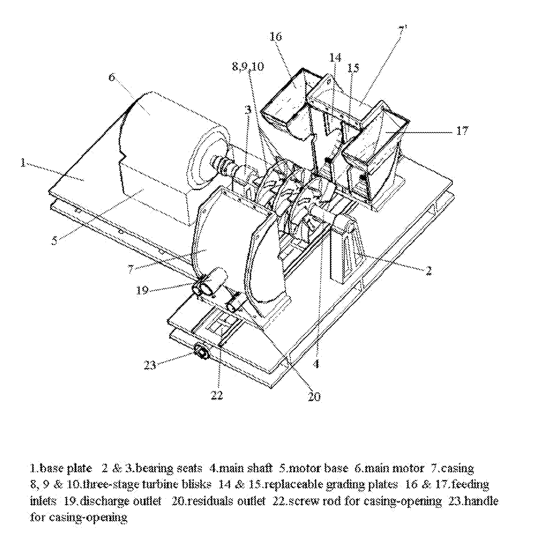
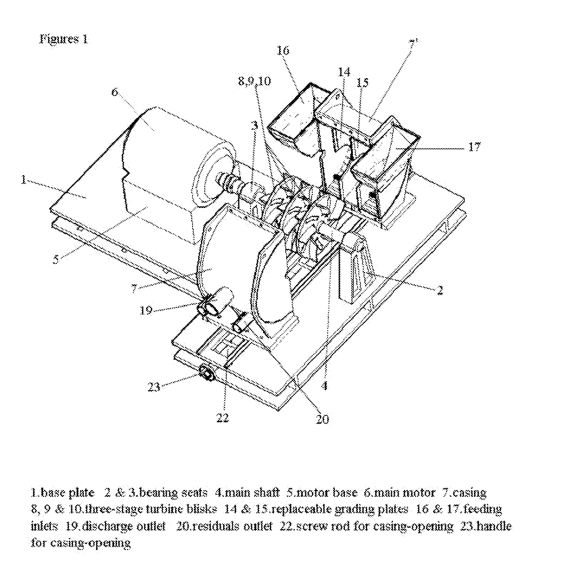
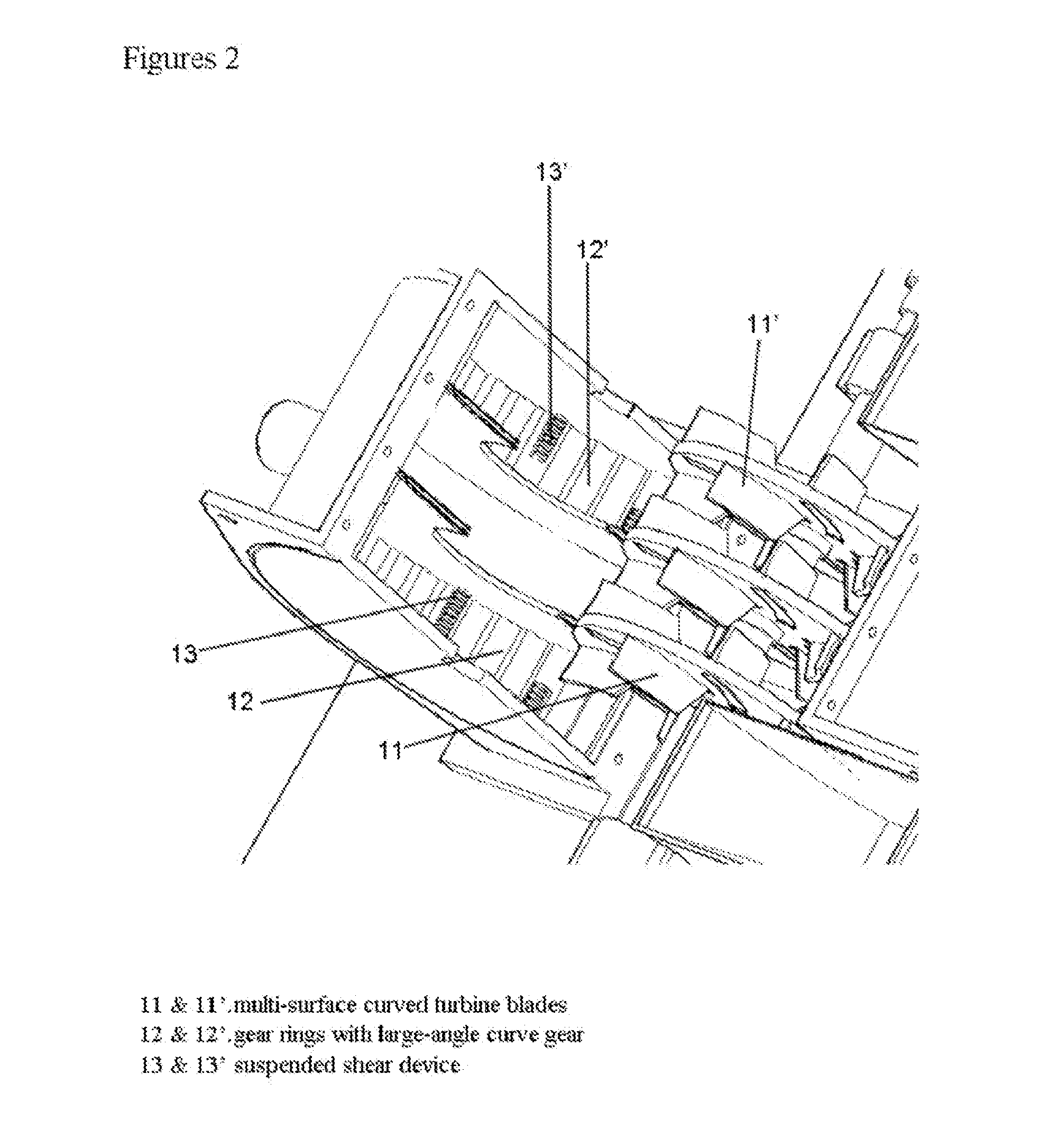
[0023]The pulverizer adopts the integral design of three turbines and three cavities, wherein the left and the right cavities are grinding cavities with residuals discharger. The middle cavity is discharge cavity. Materials enter from the central feeding inlet of the outer sides of the left and the right grinding cavities, after they enter the cavities, they will quickly move towards the cyclone troposphere on the periphery of the grinding cavities under the function of cyclone centrifugal force generated by high speed rotation of the solid turbine. Since the turbine always keeps a certain speed (the rotary speed can be adjusted by frequency converter in accordance with the fineness requirement) of high speed rotation, material particles will do constant free inertial collision and shear motion on the cyclone troposphere layer, and since the difference of the qualities of material particles, kinetic energy will be mutually transformed after collision. When large mass of particles ar...


PUM


Abstract

A mechanical pulverizer adopts multi-stage high-speed rotating turbine and special design structure to achieve ultrafine or nano pulverization. As shown in the figures, the mechanical pulverizer comprises: base plate (1), bearing seats (2 and 3), main shaft (4), motor base (5), main motor (6), casing (7 and 7′), three-stage turbine blisks (8, 9 and 10), multi-surface curved turbine blades (11 and 11′), gear rings with large-angle curved gears (12 and 12′), suspended shearing device (13 and 13′), built-in, unpowered and replaceable grading plates, (14 and 15), feeding inlets (16 and 17), spiral feeder (18), discharge outlet (19), residuals outlet (20), nanometer filter cloth material collecting bin (21), screw rod for casing-opening (22), handle for casing-opening (23), self-pressurized automatic-control liquid nitrogen cooling device (24), and liquid nitrogen conveying pipes (25).

Description

BACKGROUND OF THE INVENTION[0001]This invention applies to superfine and Nanometer pulverization of all kinds of materials in powder industry, such as all kinds of precious metal, nonmetal mineral substances, plant fiber, industrial chemicals and so on.[0002]It is generally known that the traditional pulverizing machines, such as ball pulverizer, Raymond mill, fan mill, airflow crasher, are functioning by the principles of gravity grind, weight striking or high pressure airflow impacting to acquire superfine powder, they must have independent grading system, induced draft fan system, while airflow pulverizer even needs an independent high pressure gas generation and storage system. The major shortfalls of these traditional pulverizers usually make them poor efficient, high energy consumption, pollution from grinder surface worn residuals, and low level performance in pulverization. In consequence, the high cost on both equipment purchasing and production process impedes them to be l...

Claims


Application Information

Patent Timeline
IPC IPC(8): B02C19/06B02C23/10B02C23/04
CPCB02C13/08B02C13/09B02C13/26B02C23/10
Inventor XIAO, HANPING
Owner XIAO HANPING
Features
  • Generate Ideas
  • Intellectual Property
  • Life Sciences
  • Materials
  • Tech Scout
  • Unparalleled Data Quality
  • Higher Quality Content
  • 60% Fewer Hallucinations
Learn More