Power storage device and charging method thereof

a technology of power storage device and charging method, which is applied in the direction of secondary cell servicing/maintenance, cell components, instruments, etc., can solve the problems of reducing the capacity of the power storage device, and achieve the effects of low power consumption, high reliability, and low off-state curren

Active Publication Date: 2014-07-03
SEMICON ENERGY LAB CO LTD
View PDF12 Cites 53 Cited by
  • Summary
  • Abstract
  • Description
  • Claims
  • Application Information

AI Technical Summary

Benefits of technology

[0030]Further, a semiconductor device with low off-state current can be provided. A semiconductor device with low power consumption can be provided. Further, a semi

Problems solved by technology

Therefore, there is an imbalance in the amount of inserted and extracted lithium between the positive el

Method used


Image

  • Power storage device and charging method thereof
  • Power storage device and charging method thereof
  • Power storage device and charging method thereof

Examples


example 1

[0438]In this example, a power storage device was fabricated using lithium iron phosphate (LiFePO4) as an active material that exhibits two-phase reaction, and charge-discharge characteristics of the device were evaluated.

(Formation of Lithium Iron Phosphate)

[0439]LiFePO4 whose surface is covered with a carbon layer was used for this power storage device. LiFePO4 was formed by a solid-phase method. To prepare LiFePO4 whose surface is covered with a carbon layer, raw materials Li2CO3, FeC2O4.2H2O, and NH4H2PO4 were weighed in a dry room (with a dew point of higher than or equal to −70° C. and lower than or equal to −55° C.) so as to satisfy a molar ratio of 2:1:1.

[0440]Next, the raw materials were mixed and crushed with a ball mill. Here, a planetary ball mill was used. With the use of a 500 ml zirconia pot and 300 g of zirconia balls with a diameter of 3 mm, the raw materials with a total weight of 150 g were subjected to ball milling at a rotation speed of 300 rpm for 2 hours. In t...

example 2

[0467]In this example, variations in the current value when applying high voltage to a power storage device using lithium iron phosphate (LiFePO4) that exhibits two-phase reaction as a positive electrode active material were measured.

[0468]A CR2032 coin-type cell (with a diameter of 20 mm and a height of 3.2 mm) was fabricated and used for measurement. A positive electrode with a compounding ratio (wt %) of lithium iron phosphate covered with a carbon layer to acetylene black and PVDF of 85:8:7 was used. The thickness of an active material layer was 75 μm, the LiFePO4 content was 9.8 mg / cm2, and the single-electrode theoretical capacity was 1.67 mAh / cm2. A negative electrode with a compounding ratio (wt %) of graphite to acetylene black and PVDF of 93:2:5 was used. The thickness of an active material layer was 120 μm, the graphite content was 12 mg / cm2, and the single-electrode theoretical capacity was 4.46 mAh / cm2.

[0469]As a separator, 25-μm-thick polypropylene was used. An electro...


PUM


Abstract

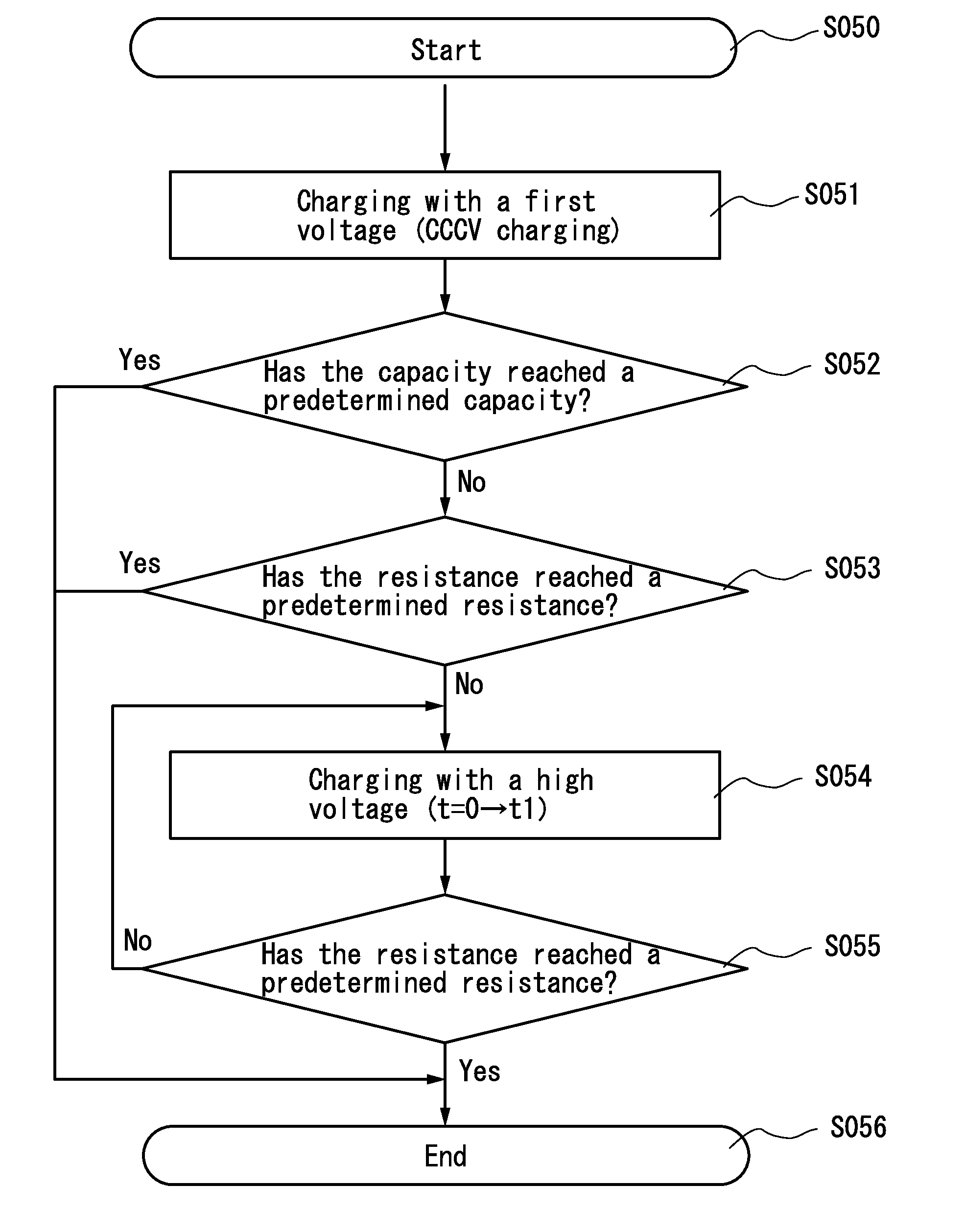
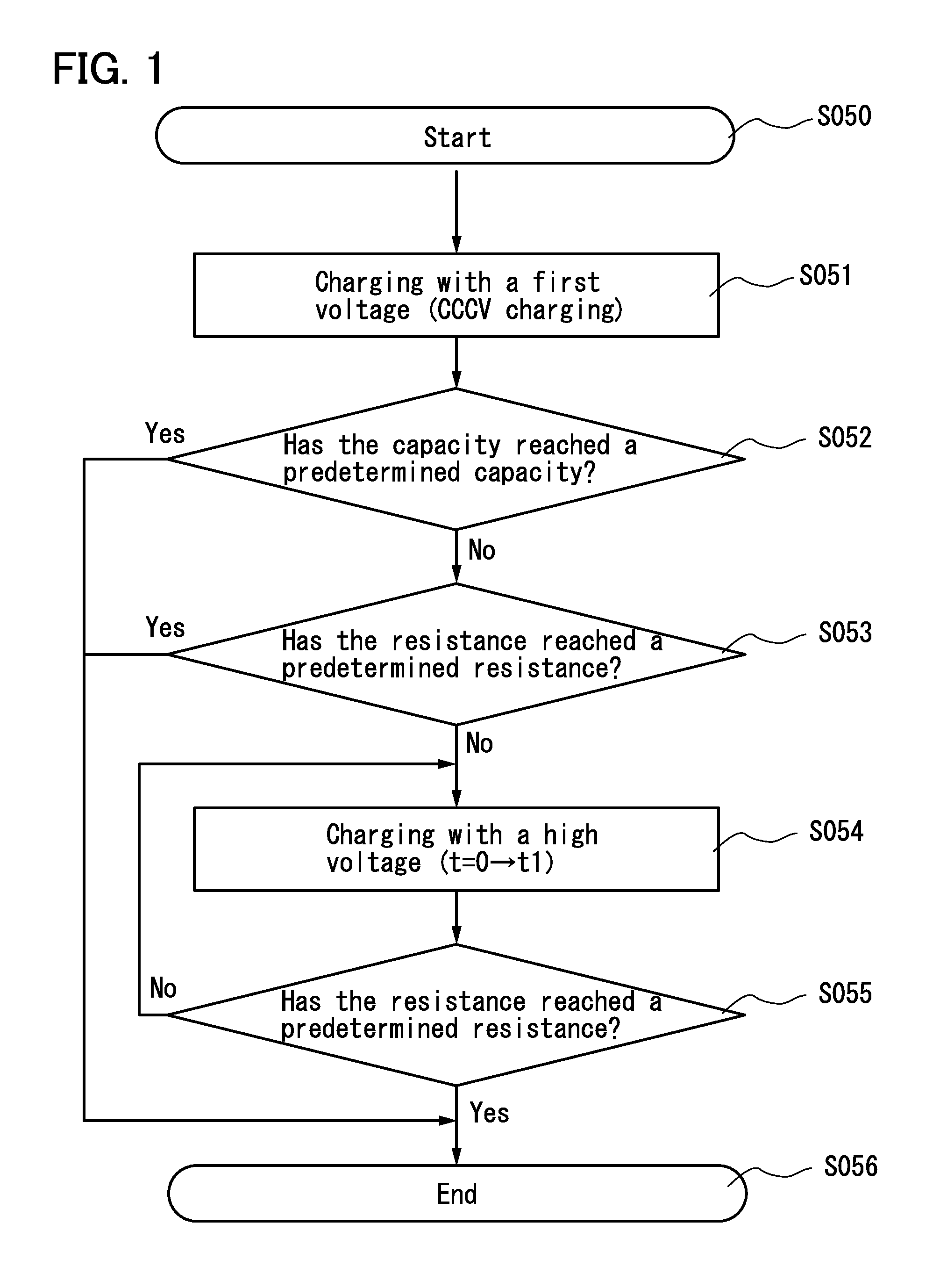
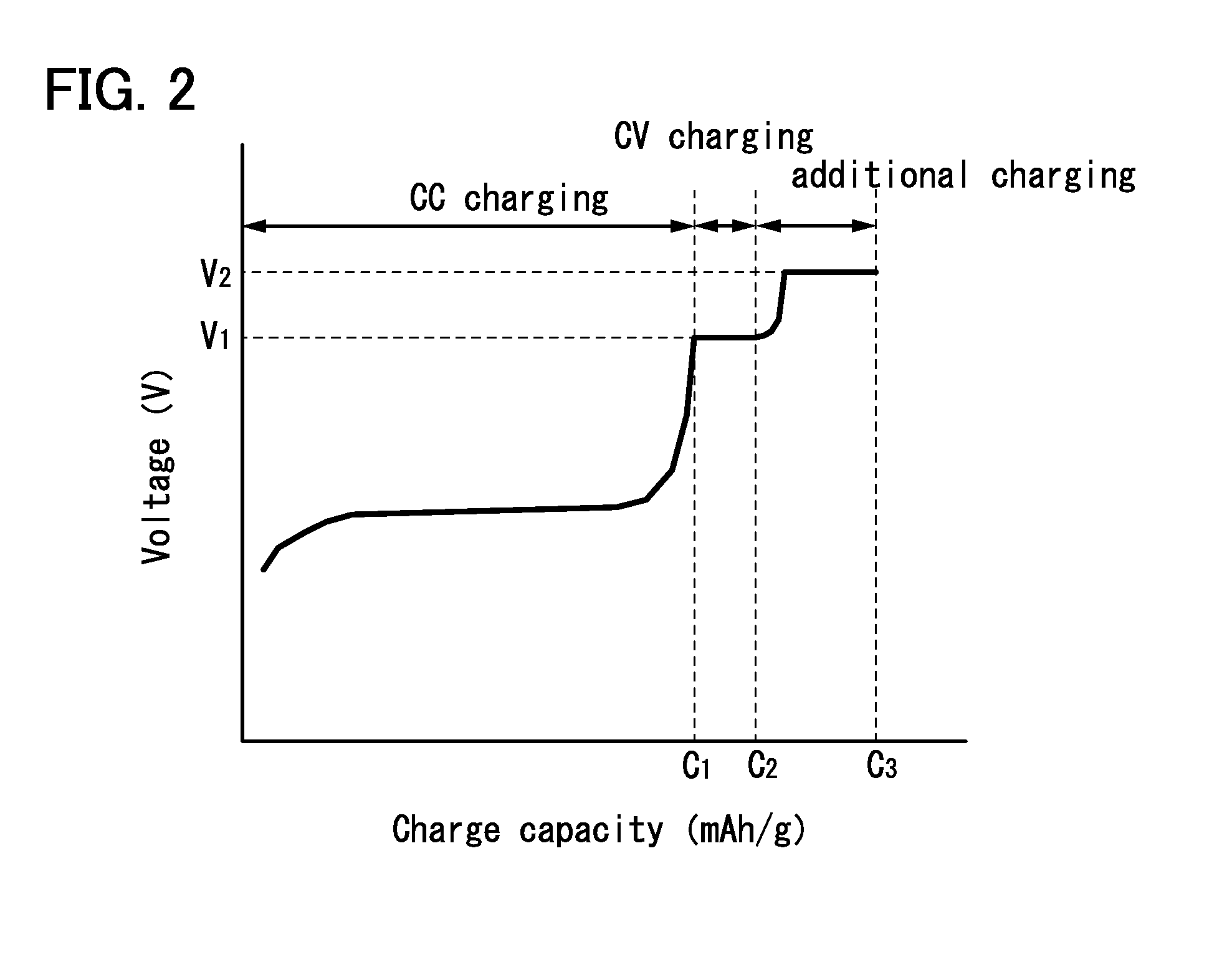
An object is to inhibit a decrease in the capacity of a power storage device or to compensate the capacity, by adjusting or rectifying an imbalance between a positive electrode and a negative electrode, which is caused by decomposition of an electrolyte solution at the negative electrode. Provided is a charging method of a power storage device including a positive electrode using an active material that exhibits two-phase reaction, a negative electrode, and an electrolyte solution. The method includes the steps of, after constant current charging, performing constant voltage charging with a voltage that does not cause decomposition of the electrolyte solution until a charging current becomes lower than or equal to a lower current value limit; and after the constant voltage charging, performing additional charging with a voltage that causes decomposition of the electrolyte solution until a resistance of the power storage device reaches a predetermined resistance.

Description

BACKGROUND OF THE INVENTION[0001]1. Field of the Invention[0002]The present invention relates to an object (a product including a machine, a manufacture, and a composition of matter) and a method (a process including a simple method and a production method). In particular, one embodiment of the present invention relates to a power storage device, a power storage system, a semiconductor device, a display device, a light-emitting device, and an electrical appliance, and further to a manufacturing method thereof and a driving method thereof. More specifically, one embodiment of the present invention relates to a power storage device, a power storage system, a semiconductor device, a display device, a light-emitting device, and an electrical appliance which include an oxide semiconductor, and further to a manufacturing method thereof and a driving method thereof. In particular, one embodiment of the present invention relates to a power storage device and a charging method thereof.[0003]...

Claims


Application Information

Patent Timeline
IPC IPC(8): H02J7/00
CPCH02J7/0057H01M10/44H01M4/625H01M10/0525B60L53/14B60L53/12H02J7/0069Y02E60/10Y02T10/70Y02T90/14Y02T10/7072G01R31/382H02J7/00H02J7/0068
Inventor MOMO, JUNPEIMIYAKE, HIROYUKITAKAHASHI, KEI
Owner SEMICON ENERGY LAB CO LTD
Why Eureka
Try Eureka