Method and arrangment for remote controlling a power consumption state of a network device
a technology of network devices and power consumption states, applied in the direction of power supply for data processing, instruments, computing, etc., can solve the problems of time-consuming restart process, reducing work efficiency, and complicating the technical process of testing a devi
- Summary
- Abstract
- Description
- Claims
- Application Information
AI Technical Summary
Benefits of technology
Problems solved by technology
Method used
Image
Examples
case 3
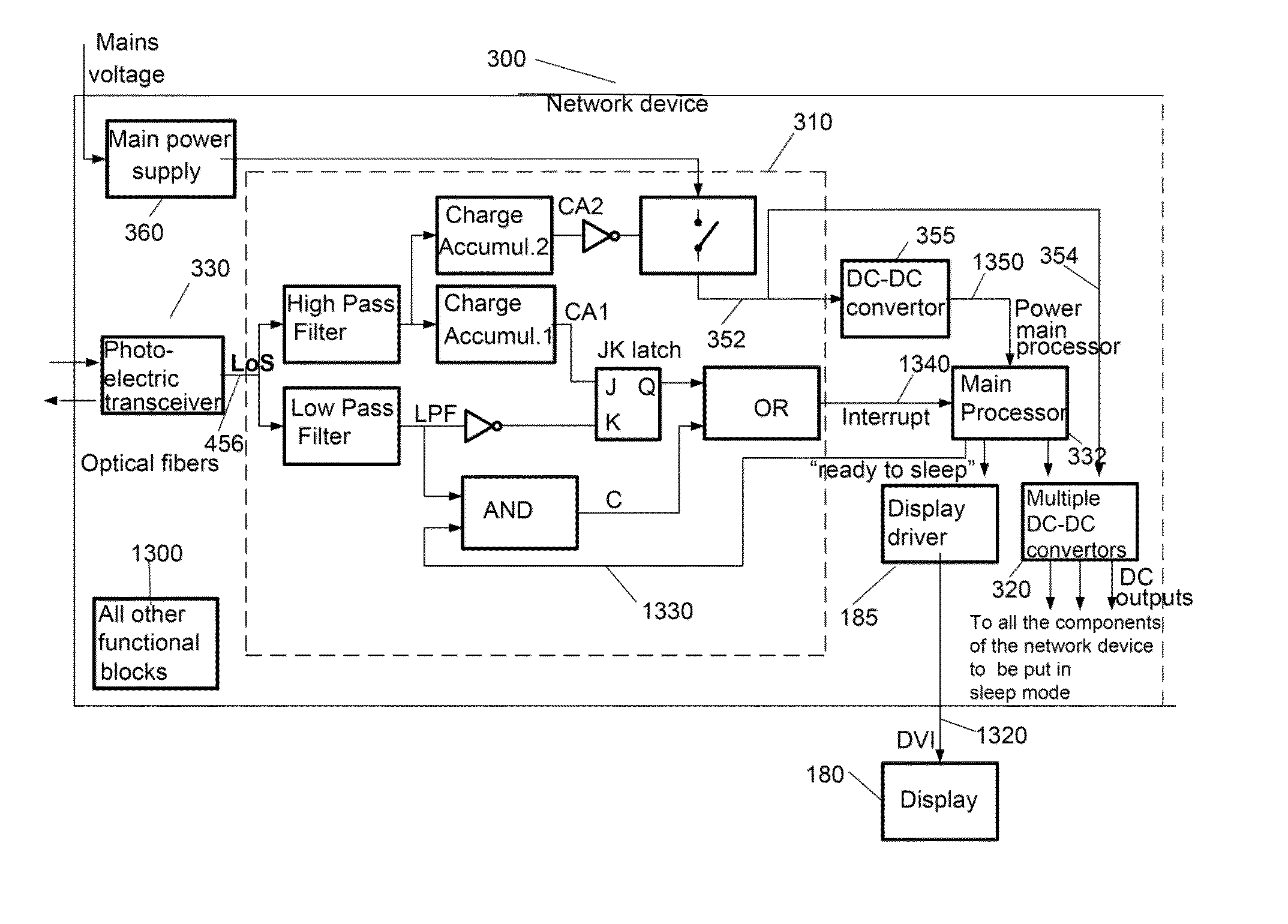
[0103]E.g. when the LoS output 456, from the photo-electric transceiver 330, provides a first specific signal such as n1 pulses, for example n1=5 at a frequency of for example 0.1 Hz, then the interrupt line 1340 to the main processor 332 will e.g. show a transition from LOW to HIGH after the n1th pulse, and stay HIGH, e.g. by proper dimensioning of the time constant of the low pass filter and charge accumulator 1. The corresponding waveforms are shown in FIG. 14. It is important to remark that the output of the LPF should become HIGH (caused by a HIGH LoS) before the output of the charge accumulator 1 becomes LOW.
[0104]An interrupt service routine will be preferably started upon receiving this interrupt signal 1340. The main processor 332 executes this interrupt service routine and will switch off the power output lines of 320 to all the electronic devices that must be switched off during the sleep mode. This includes all the components except the main processor 332, the controller...
case 6
[0105]The transition of the LoS line from HIGH to LOW, caused by the network switch, will bring the interrupt line of the main processor from HIGH to LOW (waveform FIG. 14). When the interrupt line 1340 of the main processor transitions from HIGH to LOW, then the main processor 332 will preferably become active again and will execute a software routine to power up again all the electronic devices that previously were switched off from the power. In this embodiment this is done by enabling again the DC-DC convertors that were switched off in case 3. Also the related device such as the display device or the image capturing device will be powered up via for example the VESA DPMS in case of the display device, and via for example USB in case of the image capturing device.
case 4
[0106]When the sleep mode controller 310 receives a second specific signal such as a series of n2=10 pulses of for example a frequency of 0.1 Hz, then a power cycle will be initiated after the 9th pulse. The power line 352 to the main processor 332 will be shut down for a time of for example 35s. After this time the power to the main processor 332 will be available again and the main processor will start up the complete network device and finally come again in the normal mode. The corresponding waveforms are shown in FIG. 15. As already explained earlier a power cycle will be executed when the network device is in the freeze state.
[0107]As already explained earlier a power cycle will beneficially be executed when the network device is in the freeze state.
PUM
 Abstract
Description
Claims
Application Information
 - R&D
- Intellectual Property
- Life Sciences
- Materials
- Tech Scout
- Unparalleled Data Quality
- Higher Quality Content
- 60% Fewer Hallucinations
Browse by: Latest US Patents, China's latest patents, Technical Efficacy Thesaurus, Application Domain, Technology Topic, Popular Technical Reports.
© 2025 PatSnap. All rights reserved.Legal|Privacy policy|Modern Slavery Act Transparency Statement|Sitemap|About US| Contact US: help@patsnap.com


