System and method for removing sludge from a storage tank

a technology of sludge and storage tank, which is applied in the direction of cleaning process and apparatus, cleaning using liquids, and separation processes, etc., can solve the problems of high abrasive particles, difficult to mobilize or fluidize with normal pumping systems, and increase turbulence,

Inactive Publication Date: 2014-07-10
TRADEBE ENVIRONMENTAL SERVICES
View PDF7 Cites 9 Cited by
  • Summary
  • Abstract
  • Description
  • Claims
  • Application Information

AI Technical Summary

Benefits of technology

[0007]Another significant advantage of the present invention is its ability to extract and process sludge containing catalyst fines. This is sludge that builds up in tanks or vessels that contains crude oil fractions and fine particles resulting from erosion of catalysts normally used in oil refinery processes. These particles are highly abrasive and difficult to mobilize or fluidize with normal pumping systems.
[0008]Another advantage of the present invention is that entry to the tank by workers is not required. The system and method permits the use of equipment that is located exterior to the tank, and then inserted, as through an access opening in the side of the tank. In association with the foregoing advantage, the present invention further provides an improved hydraulic equipment positioning arrangement, for both positioning, inserting and withdrawing the conduit structure and end effectors for accessing the sludge or sediment. This further may include a leveling element preferably in the form of a hydraulic system that operates to move the assembly in a vertical plane.
[0009]Yet another advantage is that the contents of the tank need not be pumped down to the level of the sediment or sludge, in order to remove the latter. In conjunction with the foregoing, a sonar mechanism is preferably provided as part of the system, which is used to take readings to map the topography of the sediment. In operation, this may be done on a periodic basis during the course of sediment removal, in order to direct operations and track progress. This would further allow the use of more directionalized handling of the sludge removal equipment, such as aiming of the end effectors. End effectors may include directional nozzles, as would be used to direct working fluids, for sludge breakup, dissolution and better location of pumping systems.
[0010]Still another perceived innovation of the present invention is the use of a single high pressure hydraulic fluidization pump to operate the working fluid. This improves upon the prior art system of multiple pumps and hydraulic pack systems.
[0011]As a particularly useful end effector, the improved system and method may employ a Penberthy nozzle. This is used to increase turbulence, as the nozzle effects spraying, mixing and pumping of the working fluid and entrained sludge, essentially simultaneously. Another type of end effector contemplated would be directional nozzles as well, as articulation nozzles. These would most preferably be part of a modular arrangement, whereby a desired end effector could be readily added in place of another.
[0012]Yet another innovation of the present invention is the use of a pump grinder mechanism. The pump grinder allows for grinding of sludge solids in the pumping process. Still further, a positive displacement piston pump may be employed in conjunction with the pump grinder.

Problems solved by technology

These particles are highly abrasive and difficult to mobilize or fluidize with normal pumping systems.

Method used


Image

  • System and method for removing sludge from a storage tank
  • System and method for removing sludge from a storage tank
  • System and method for removing sludge from a storage tank

Examples


Embodiment Construction

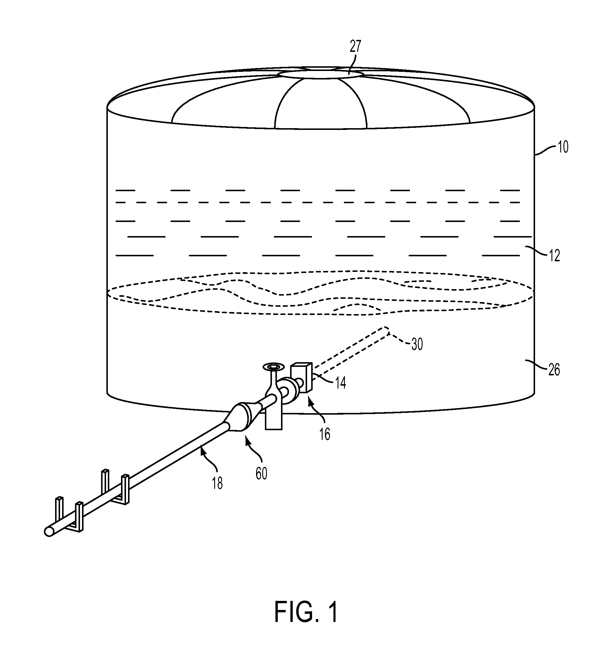
[0035]Turning now to FIG. 1, the system is shown as it would be used with a large tank, such as one that would contain a liquid hydrocarbon material: in this particular application, the storage tank 10 contains crude oil 12. Such a storage container would typically have an access opening or manway 14 with a gate valve assembly (broadly indicated at 16) associated therewith. The access opening and gate valve assembly are standard, typically also having an isolation barrel secured to the gate valve with appropriate flanges, secured in a suitable manner. See, for instance, the disclosure of U.S. Pat. No. 6,142,160 with regard to such standard details.

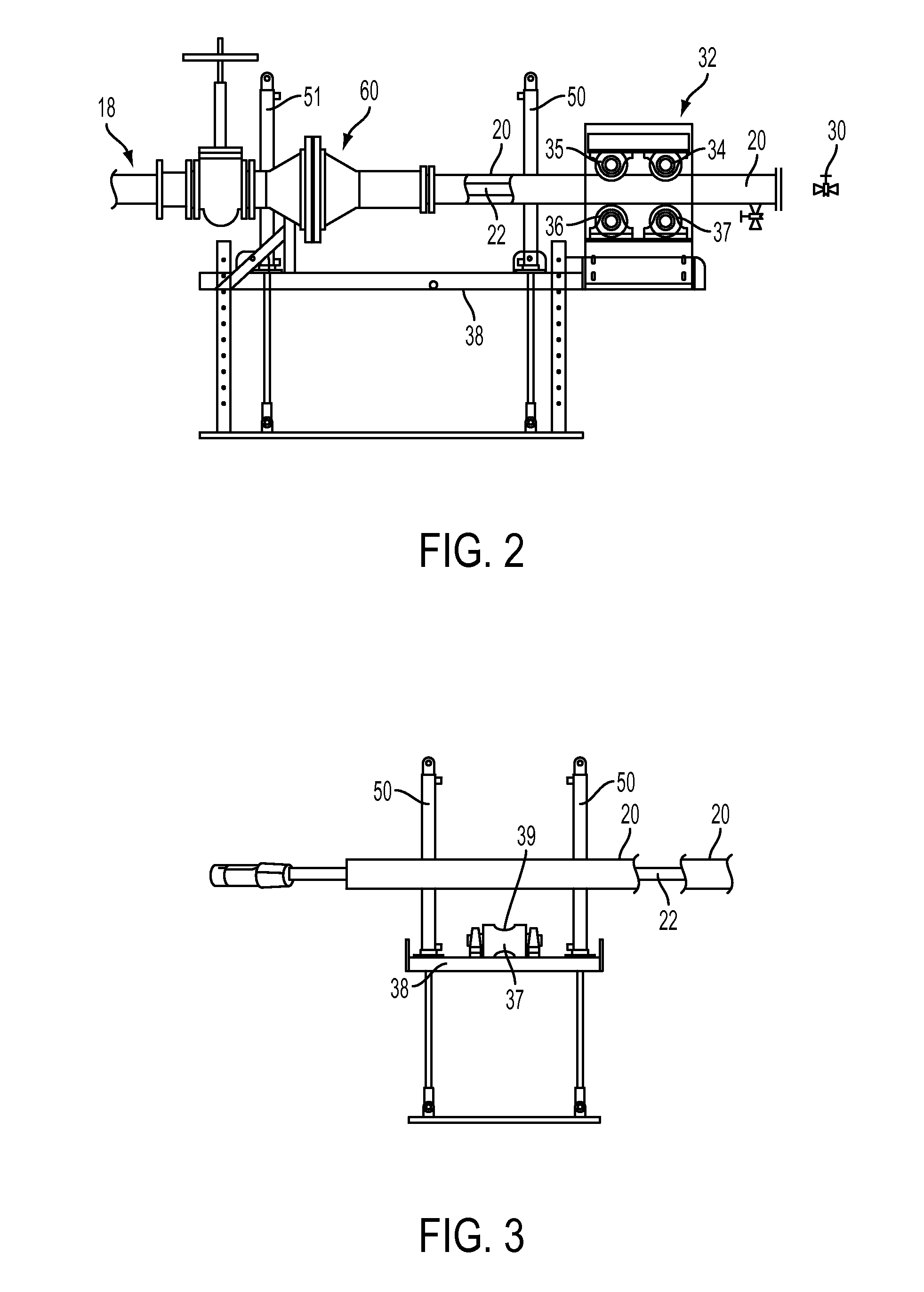
[0036]As will be described more specifically hereafter, the inventive system utilizes a concentric piping arrangement 18 having inner 20 and outer 22 pipes (FIG. 2). Piping 18 is inserted through the gate valve assembly 16 into the tank 10, at a level where the end of the piping will be in, or in the vicinity of, sediment or sludge 26 in t...


PUM

PropertyMeasurementUnit
pressureaaaaaaaaaa
pressureaaaaaaaaaa
lengthaaaaaaaaaa

Abstract

The system and method permits the use of equipment that is located exterior to a container, such as a tank container liquid hydrocarbon material within which a sludge deposit has accumulated, and then inserted, as through an access opening in the side of the tank. In addition to other innovations, an improved hydraulic equipment positioning arrangement is provided, for both positioning, inserting and withdrawing the conduit structure and end effectors for accessing the sludge or sediment, which may include a leveling element preferably in the form of an hydraulic system that operates to move the assembly in a vertical plane as well as a rotary driven hydraulic system for driving the conduit structure along a long axis.

Description

BACKGROUND OF THE INVENTION [0001]The present invention generally relates to a system and method for the removal of sediment, or sludge, from a container, such as a large tank used to store hydrocarbon fluids. Such tanks would typically be the kind that are used in petroleum refineries or chemical plants, for storing large quantities of hydrocarbon liquids such as crude oil and derivatives thereof.[0002]These types of hydrocarbon liquids will often contain particulates and different phases which may cause layering or stratification. Over time, these particulates and heavier phases accumulate on the floor or base of the tank, forming a sludge. Sludge and sediment are used interchangeable herein. When the accumulation becomes more than tolerable, i.e., excessive, then the sludge must be removed.[0003]It is known to remove the sludge by agitating the sludge in a manner to suspend the sludge in a form where the sludge can then be sucked out of the tank. This can be done by injecting a w...

Claims


Application Information

Patent Timeline
Patent Type & Authority Applications(United States)
IPC IPC(8): B08B9/093
CPCB08B9/0933B01D21/245
Inventor FALLON, JAMES T.MILLER, III, JAMES W.NUSIMOVICH, SERGIO
Owner TRADEBE ENVIRONMENTAL SERVICES
Why Eureka
Try Eureka