Electronic device

a technology of electrochemical devices and electrodes, applied in the direction of electrochemical generators, secondary cell servicing/maintenance, transportation and packaging, etc., can solve the problems of affecting the service life of batteries. , to achieve the effect of reducing the degradation degree and removing the degradation of electrodes

Active Publication Date: 2014-07-17
SEMICON ENERGY LAB CO LTD
View PDF14 Cites 41 Cited by
  • Summary
  • Abstract
  • Description
  • Claims
  • Application Information

AI Technical Summary

Benefits of technology

[0007]In view of the above, an object of the present invention is to prevent degradation of a battery or to reduce the degree of the degradation and to maximize and maintain charge and discharge performance of the battery for a long time.
[0100]With the use of the technical idea of utilizing the mechanism of formation of dross and the mechanism of dissolution of the dross, even when an electronic device is partly degraded, the degree of the degradation can be reduced and the electronic device can be brought into a state close to an initial state, ideally, the electronic device can be returned to the initial state.

Problems solved by technology

Further, batteries are electrochemical devices whose lifetimes are difficult to estimate individually in advance.
Although batteries are charged and discharged without any problem when manufactured and thus shipped as quality products, there are some defective products which suddenly do not function as batteries later from any cause.
In particular, there is a problem in that the maintenance of a fixed power source or power storage equipment requires considerable cost and time.

Method used


Image

  • Electronic device
  • Electronic device
  • Electronic device

Examples


embodiment 1

[0135]A battery of one embodiment of the present invention is described in detail below.

[A-1. Fabrication of Evaluation Cell]

(Formation of Positive Electrode)

[0136]To form a positive electrode of an evaluation cell, first, lithium iron phosphate (LiFePO4) whose surface was provided with a carbon layer by a method described in this embodiment and N-methyl-2-pyrrolidone (NMP) as a polar solvent were prepared. These were stirred and mixed in a mixer at 2000 rpm for 5 minutes, and ultrasonic vibration was applied for 3 minutes. Further stirring and mixing were performed in a mixer at 2000 rpm for a minute. The same process was repeated five times.

[0137]Next, graphene oxide was added to this mixture, and stirring and mixing of the mixture in a mixer at 2000 rpm for 3 minutes were performed eight times. While being mixed eight times, the contents in a container were stirred with a spatula. Then, half of the total amount of PVDF used as a binder was added and the mixture was stirred and mi...

embodiment 2

[0163]In this embodiment, description is made on an example of a reaction product which is a lithium deposit.

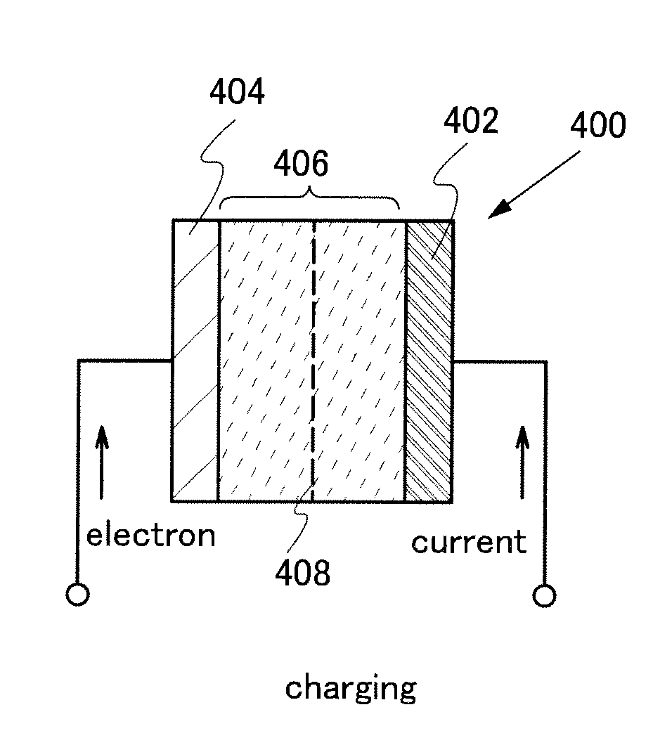
[0164]As illustrated in FIG. 10A, when a lithium-ion secondary battery is charged, lithium ions that are carrier ions are extracted from a positive electrode active material 802 over a positive electrode current collector 801 included in a positive electrode 800, and move to a negative electrode active material 805 over a negative electrode current collector 804 included in a negative electrode 803. A current flow direction 820 at the time of charging can be shown by an arrow in FIG. 10A. Then, the lithium ions are inserted into the negative electrode active material 805 to provide a negative electrode active material 821 into which the lithium ions are inserted (see FIG. 10B).

[0165]However, when a current value exceeds the allowable value of the negative electrode, an abnormal state where lithium 806 is deposited on a surface of the negative electrode active material 805 is ...

embodiment 3

[0190]Next, structures of nonaqueous secondary batteries are described with reference to FIGS. 15A to 15C and FIGS. 16A and 16B.

[0191]FIG. 15A is an external view of a coin-type (single-layer flat type) lithium-ion secondary battery, part of which illustrates a cross-sectional view of the coin-type lithium-ion secondary battery.

[0192]In a coin-type secondary battery 950, a positive electrode can 951 serving also as a positive electrode terminal and a negative electrode can 952 serving also as a negative electrode terminal are insulated and sealed with a gasket 953 formed of polypropylene or the like. A positive electrode 954 includes a positive electrode current collector 955 and a positive electrode active material layer 956 which is provided to be in contact with the positive electrode current collector 955. A negative electrode 957 includes a negative electrode current collector 958 and a negative electrode active material layer 959 which is provided to be in contact with the neg...


PUM

PropertyMeasurementUnit
thicknessaaaaaaaaaa
interlayer distanceaaaaaaaaaa

Abstract

Degradation of a battery is prevented or the degree of the degradation is reduced, and charge and discharge performance of the battery is maximized and maintained for a long time. A reaction product, which is formed on an electrode surface and causes various malfunctions and degradation of a battery such as a lithium-ion secondary battery, is dissolved by application of electrical stimulus, specifically, by applying a signal to supply a current reverse to a current with which the reaction product is formed (reverse pulse current).

Description

TECHNICAL FIELD[0001]The present invention relates to an object, a method, or a manufacturing method. In addition, the present invention relates to a process, a machine, manufacture, or a composition of matter. In particular, the present invention relates to, for example, a power storage device, a secondary battery, a driving method thereof, or a fabrication method thereof. In particular, the present invention relates to, for example, an electronic device and a method for charging an electronic device. In addition, the present invention relates to a system having a function of reducing the degree of degradation of an electronic device.[0002]Note that an electronic device in this specification generally means a device that can operate by utilizing a battery (also referred to as a power storage device), a conductive layer, a resistor, a capacitor, and the like.BACKGROUND ART[0003]A lithium-ion secondary battery, which is one of batteries, is used in a variety of applications including...

Claims


Application Information

Patent Timeline
Patent Type & Authority Applications(United States)
IPC IPC(8): H02J7/00H01M4/13H02J7/04
CPCH02J7/0052H01M10/0525H01M10/4235H01M10/44H02J7/0069Y02E60/10H02J7/00H02J7/0042
Inventor YAMAZAKI, SHUNPEI
Owner SEMICON ENERGY LAB CO LTD
Why Eureka
Try Eureka