Processing apparatus and device manufacturing method

a technology of processing apparatus and manufacturing method, which is applied in the direction of photomechanical apparatus, manufacturing tools, instruments, etc., can solve the problems of increasing the weight of the object conveyed by the robot, the warping of the object due to this distortion, and the sequence may stop, so as to achieve high throughput

Active Publication Date: 2014-07-17
CANON KK
View PDF1 Cites 31 Cited by
  • Summary
  • Abstract
  • Description
  • Claims
  • Application Information

AI Technical Summary

Benefits of technology

[0009]The present invention provides a technique of simultaneously achieving high throughput and recovery of a substrate chuck failure of a chuck.

Problems solved by technology

A wafer may warp due to this distortion.
Failing in coping with the warping amount of the wafer, an error may occur in vacuum chuck of the wafer chuck, and the sequence may stop.
When the wafer warps, a local distortion occurs in the wafer on the wafer chuck, affecting AGA measurement or scan exposure.
In the apparatuses described in Japanese Patent Laid-Open Nos. 2001-284434 and 2003-234392, however, since the periphery pressing member or pressing plate configured to correct the warp of the wafer is provided on the wafer conveying robot, the weight of the object conveyed by the robot increases.
Hence, when no chuck error exists, it is difficult to convey the wafer at a high speed and accuracy.
In addition, when correcting the warp of the wafer by the periphery pressing member or pressing plate to cope with a chuck error, subsequent wafers cannot be prepared.
Hence, the lot processing takes a long time.

Method used


Image

  • Processing apparatus and device manufacturing method
  • Processing apparatus and device manufacturing method
  • Processing apparatus and device manufacturing method

Examples


first embodiment

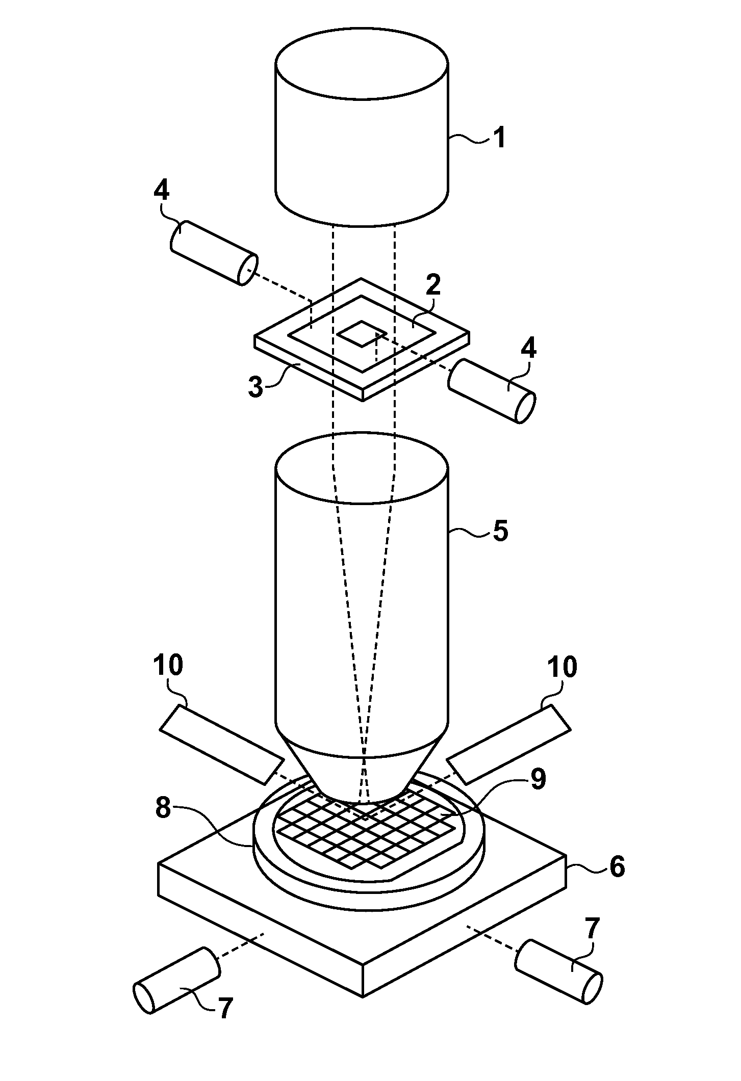
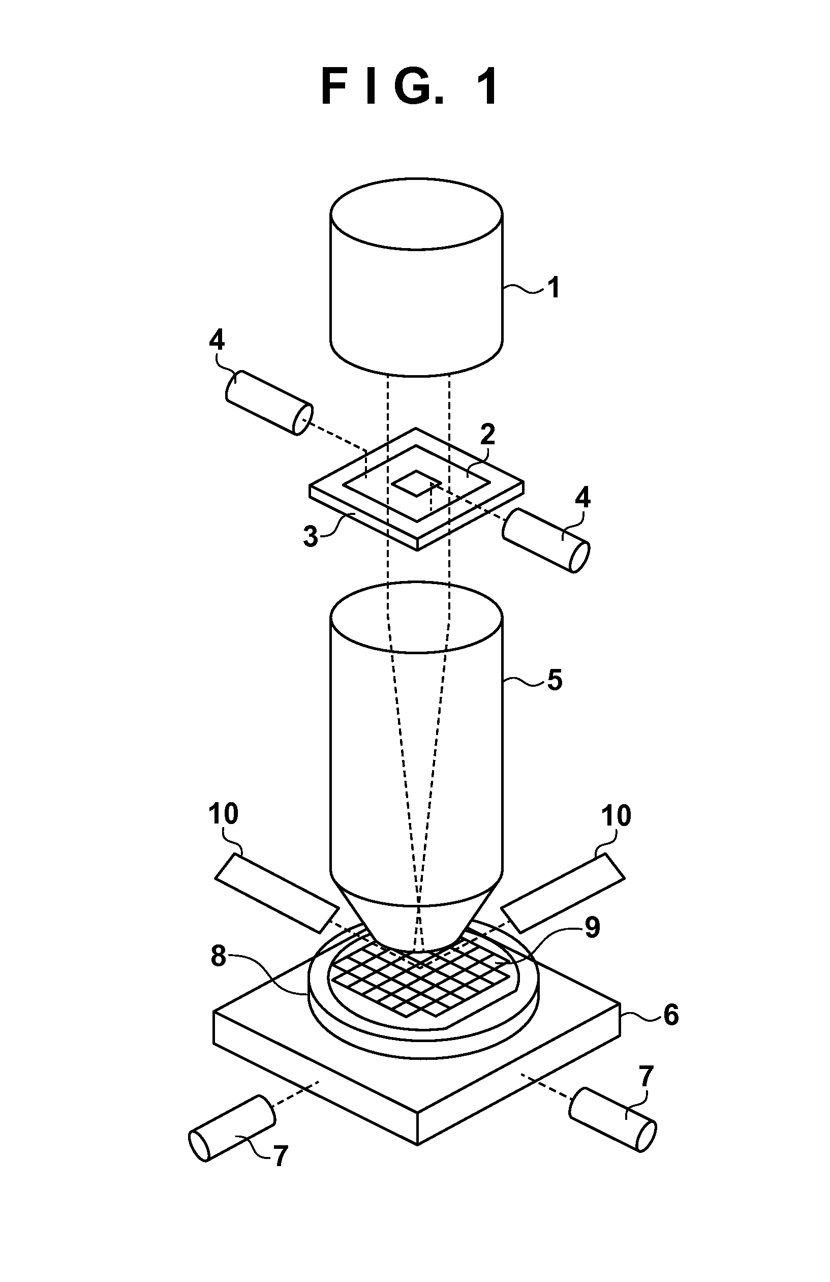
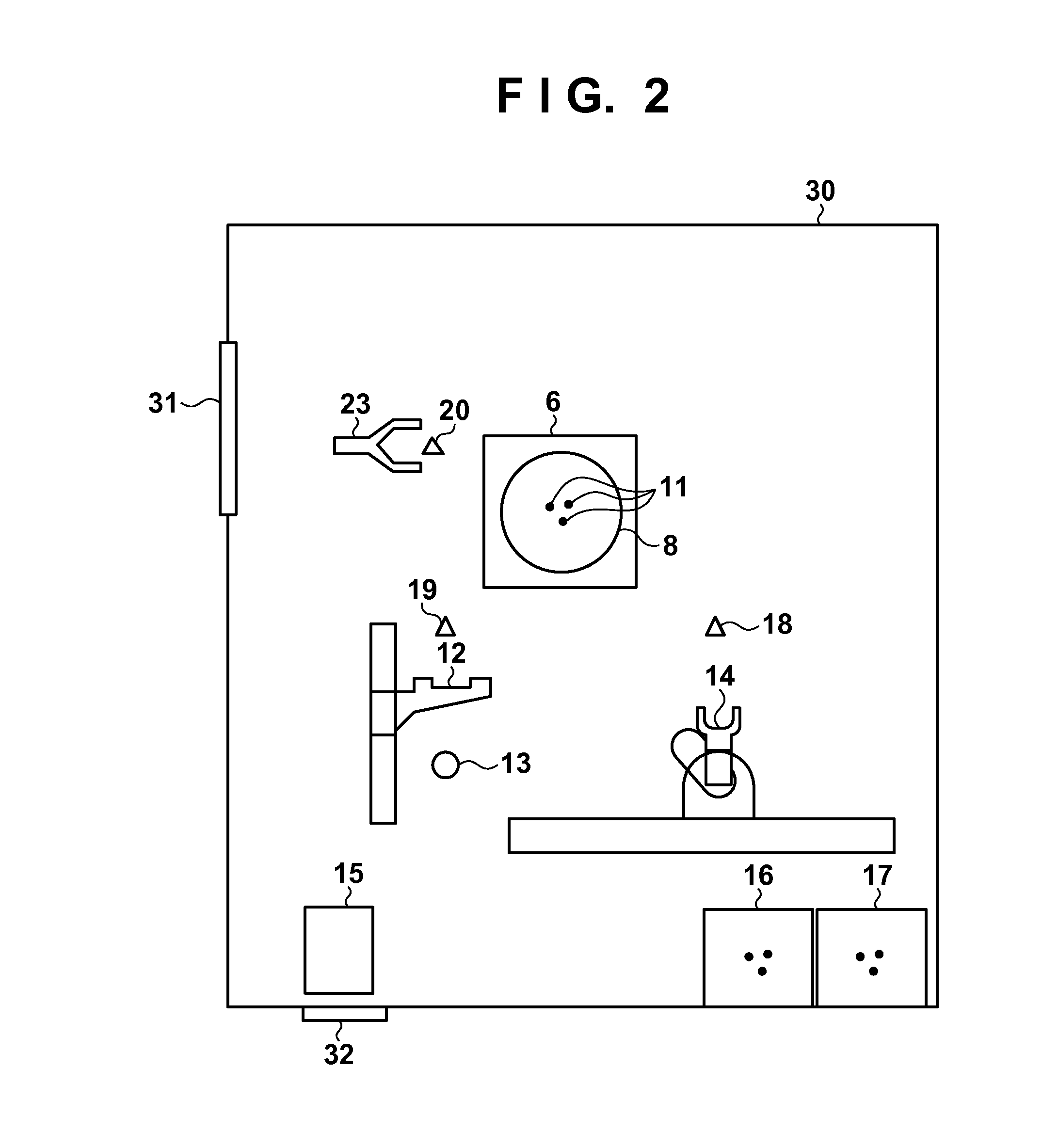
[0032]FIG. 2 is a schematic view showing an apparatus viewed from the upper side, placing focus on portions concerning conveyance of a wafer 9 and conveyance of members configured to recover a chuck failure of the wafer 9 by a wafer chuck 8. The exposure apparatus includes a chamber 30 with a door 31, the wafer chuck 8, three pins 11, a wafer stage 6, a wafer load station 16, a wafer unload station 17, a controller 15, and a pre-alignment unit 13. The exposure apparatus also includes a wafer conveying robot hand 14, a wafer feeding hand 12, and a robot hand 23. The chamber 30 maintains the exposure environment at predetermined temperature and humidity. The wafer chuck 8 vacuum-chucks the wafer 9 under the projection exposure lens 5. The three pins 11 are vertically driven to transfer the wafer 9 to the wafer chuck 8. The wafer stage 6 integrally moves the wafer 9, the wafer chuck 8, and the three pins 11 in two, X and Y directions within the X-Y plane. The wafer 9 that has not under...

second embodiment

[0049]The second embodiment will be described. In the second embodiment as well, the arrangements shown in FIGS. 1 and 3 are applicable, as in the first embodiment. FIG. 8 is a schematic view showing an apparatus viewed from the upper side, placing focus on portions concerning conveyance of a wafer 9 and conveyance of members configured to recover a chuck failure. The second embodiment is different from the first embodiment shown in FIG. 2 in that a reject carrier 21 and a stocker 22 are provided. The reject carrier 21 stores the wafer 9 in which an abnormality has occurred during exposure processing separately from the wafer 9 that has normally undergone exposure processing. In addition, the reject carrier 21 is used to store a special wafer for the maintenance of the apparatus. The stocker 22 stores a pressing plate 24, a foreign substance removing member 25, and an interchangeable wafer chuck 26 which correspond to the members configured to recover a chuck failure. The pressing p...

third embodiment

[0058]The third embodiment will be described. The arrangements are the same as in the second embodiment except FIGS. 13 and 14, and a description thereof will be omitted. In addition, the flowchart of FIG. 13 is the same as FIG. 12 except a wafer chuck exchange sub-process of step S400, and a description of processes other than step S400 will be omitted. FIG. 13 is a flowchart when chuck failure recovery processing includes exchange processing of a wafer chuck 8. In step S204, a controller 15 confirms information representing whether a mode to execute chuck failure recovery processing by a pressing plate 24 is set. Upon determining in step S204 that the mode to execute chuck failure recovery processing by the pressing plate 24 is not set, or upon determining in step S301 that chuck cleaning has already been executed, the controller 15 executes the wafer chuck exchange sub-process in step S400.

[0059]FIG. 14 is a flowchart for explaining a sub-process of exchanging the wafer chuck 8. ...


PUM

PropertyMeasurementUnit
surface shapeaaaaaaaaaa
shapeaaaaaaaaaa
speedaaaaaaaaaa

Abstract

A processing apparatus for processing a substrate chucked by a chuck installed on a stage includes: a conveying unit configured to convey the substrate to the chuck; a robot configured to selectively convey, to the stage, a pressing member capable of pressing the substrate to reduce a warp of the substrate chucked by the chuck and a cleaning member capable of cleaning a chuck surface; and a controller configured to cause the robot holding the pressing member to execute pressing processing for correcting the warp of the substrate and cause the robot holding the cleaning member to execute cleaning processing of the chuck surface.

Description

BACKGROUND OF THE INVENTION[0001]1. Field of the Invention[0002]The present invention relates to a processing apparatus and a device manufacturing method.[0003]2. Description of the Related Art[0004]An exposure apparatus used to manufacture a semiconductor device includes a wafer conveying hand that supplies / collects a wafer to / from a wafer stage, a pre-alignment stage, a wafer stage, and a conveying robot that conveys a foreign substance removing member for a wafer chuck. The pre-alignment stage aligns a wafer using a notch or an orientation flat before moving the wafer to the wafer stage. The wafer stage holds and conveys the wafer by vacuum chuck. The surface shape of the wafer vacuum-chucked by the wafer chuck and held on the wafer stage is measured using a focus sensor. The wafer surface is located at the focus position based on the shape, and exposure is performed.[0005]Presently, a stepper that performs cell projection by reducing a conventional almost square exposure region ...

Claims


Application Information

Patent Timeline
Patent Type & Authority Applications(United States)
IPC IPC(8): B23B13/00
CPCB23B13/00H01L21/68707G03F7/707G03F7/70783G03F7/70925H01L21/67288Y10T279/34
Inventor HIRANO, SHINICHIYAMADA, KOHEI
Owner CANON KK
Why Eureka
Try Eureka