
Biological nitrogen removal feed process

a feed process and biological technology, applied in sustainable biological treatment, biological water/sewage treatment, water treatment parameter control, etc., can solve the problems of matter removal, prior art biological reactor processes do not control the flow through the reactor, and the process of biological nitrogen removal is multi-step and complex. achieve the effect of improving nitrogen removal and denitrification

Inactive Publication Date: 2014-07-31
DOBIE KEITH +2
View PDF4 Cites 1 Cited by
  • Summary
  • Abstract
  • Description
  • Claims
  • Application Information

AI Technical Summary

Benefits of technology

The present invention is a wastewater treatment system that improves upon previous designs by controlling the flow of liquid through a biological reactor. This ensures that all liquid passes through both aerobic and anoxic periods before reaching a clear well. By controlling the flow, adding air and wastewater at the right time, and maintaining optimal conditions, the system can achieve better nitrogen removal compared to uncontrolled gravity flow. The invention also requires two different environments for nitrification and denitrification, and can maximize the removal of nitrogen while eliminating the need for a supplemental electron donor.

Problems solved by technology

Biological removal of nitrogen from wastewater is a multi-step process and is fairly complex.
One of the complexities in this process is that, some of the organic matter must be removed before nitrification can occur; however, organic matter is required for denitrification.
The prior art biological reactor processes do not regulate air flow to the reactor.
Also, prior art biological reactor processes do not control the flow through the reactor.

Method used


Image

  • Biological nitrogen removal feed process
  • Biological nitrogen removal feed process

Examples


Embodiment Construction

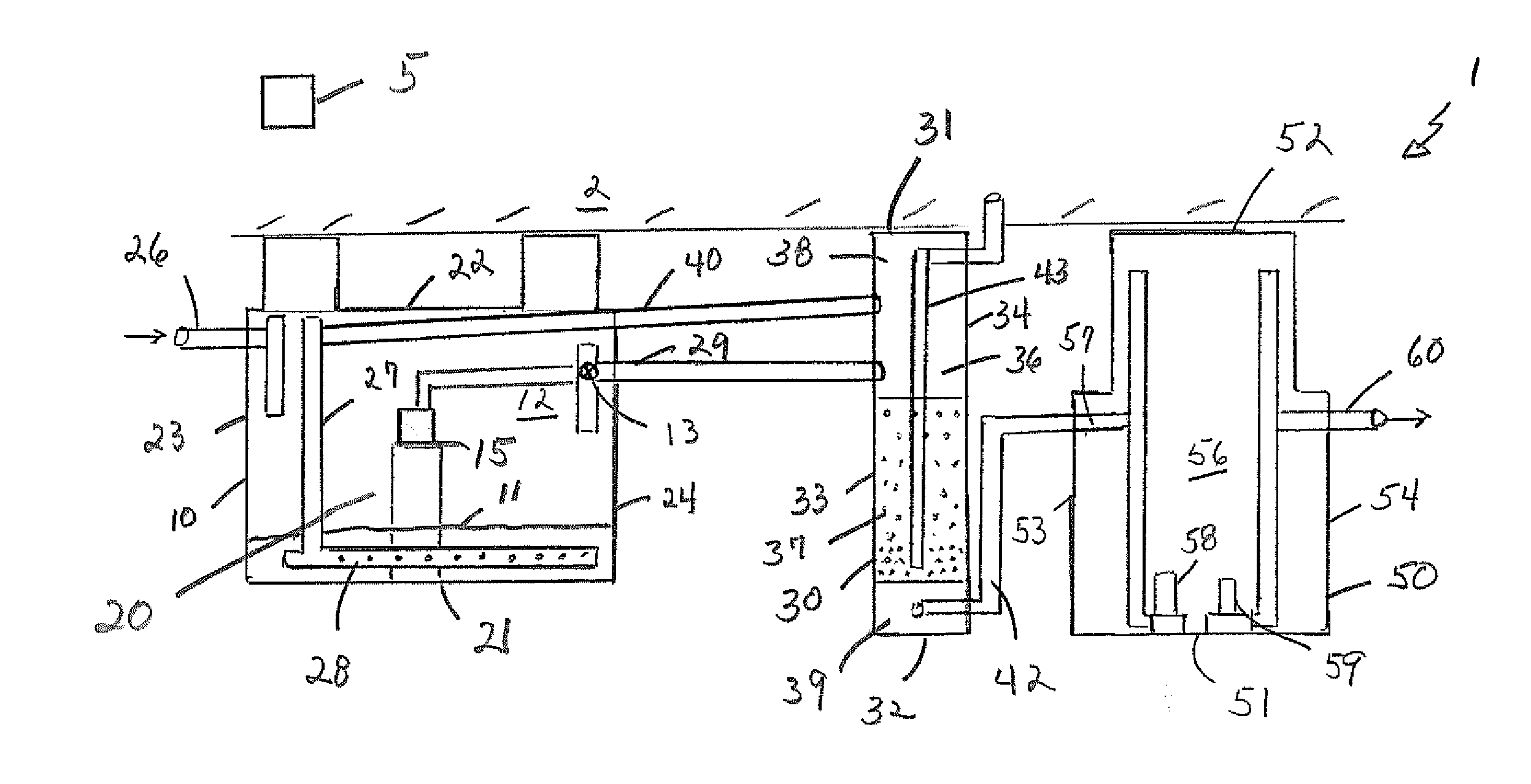
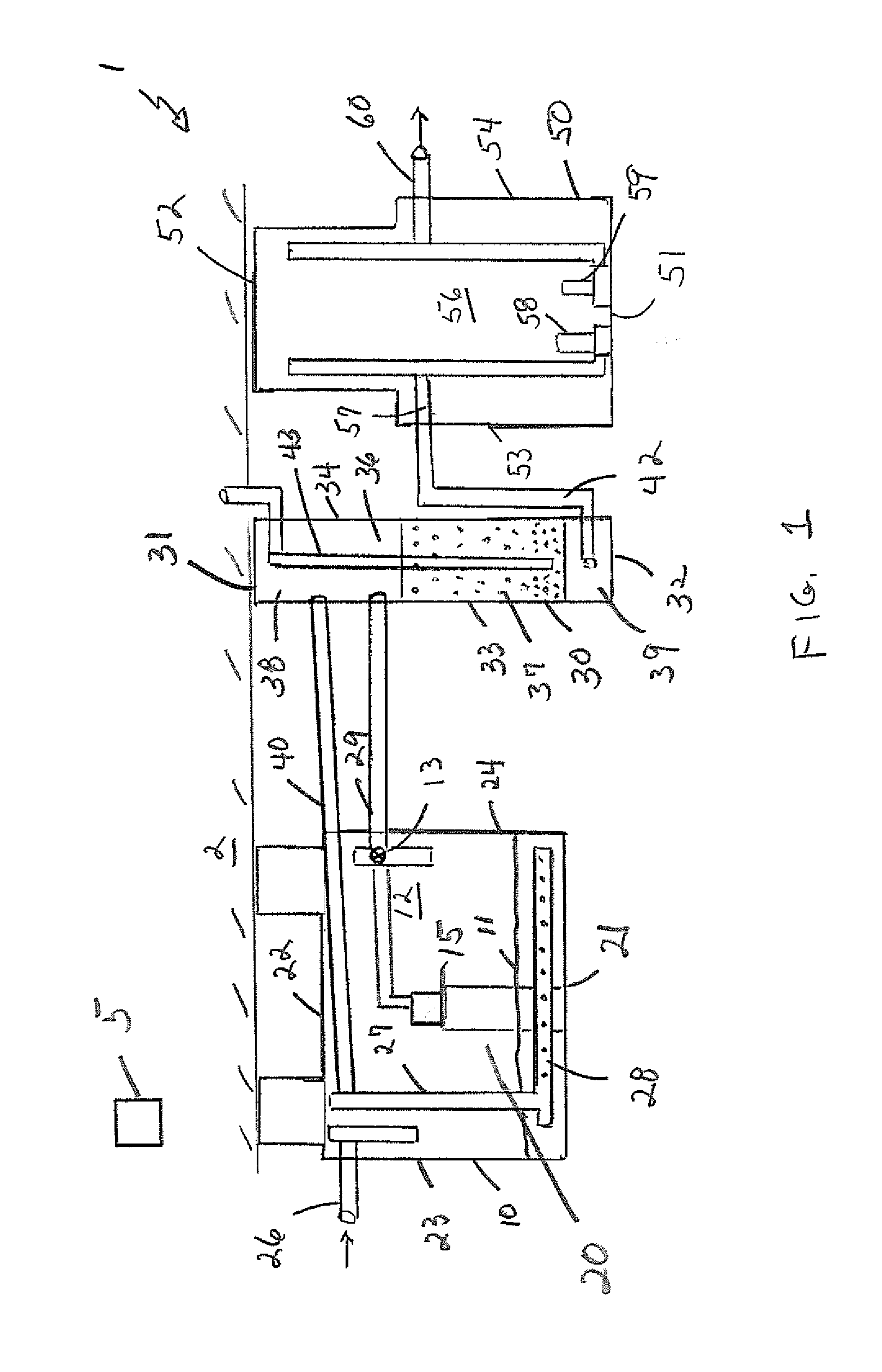
[0012]Referring to the drawings in detail wherein like elements are indicated by like numerals, there are shown a process flow for a typical wastewater treatment system 1, and the invention process installed in the anoxic tank portion of the wastewater treatment system 1.

[0013]The wastewater treatment system 1 has an anoxic tank 10 outputting to a biological reactor 30 and outputting from the reactor to a clear well 50. The anoxic tank 10, often a septic tank, typically provides primary treatment for wastewater. The anoxic tank 10 has a bottom 21, top 22, an input wall 23, an output wall 24 and two side walls 25 interconnecting the input and out put walls, said bottom, top, input wall, output wall and side walls defining an anoxic tank interior 20. The anoxic tank input 23 has a raw wastewater input pipe 26 connecting an external raw wastewater source with the anoxic tank interior 20. The input pipe 26 is located near to the anoxic tank top 22. The anoxic tank output wall has an out...


PUM


Abstract

In a wastewater treatment system comprised of an anoxic tank outputting to a biological reactor and outputting from the reactor to a clear well, a process for controlling the rate and timing of flow through the reactor by means of a floating pump within the anoxic tank. Further enhancement of denitrification is achieved by sending internal recycles into the sludge zone of the anoxic tank via a baffle positioned within the sludge layer.

Description

CROSS-REFERENCE TO RELATED APPLICATIONS[0001]Applicants claim the priority benefits of U.S. Provisional Patent Application No. 61 / 592,663, filed Jan. 31, 2012.BACKGROUND OF THE INVENTION[0002]This invention relates to waste treatment systems, and in particular, to a method for removing nitrogen from wastewater.[0003]Biological removal of nitrogen from wastewater is a multi-step process and is fairly complex. Nitrogen (in different forms) is a component of many of the molecules present in wastewater. Some examples of nitrogen-based molecules include ammonium, urea and proteins. Removal of nitrogen occurs through biochemical transformations mediated by multiple types of microorganisms, for example ammonification occurs during the oxidation of organic material containing nitrogenous compounds. As soluble organic matter is oxidized nitrogen bound compounds, such as amines (NH2−) are released and bond with H+ ions forming ammonia or ammonium.[0004]Removal of the ammonia and ammonium form...

Claims


Application Information

Patent Timeline
IPC IPC(8): C02F3/00
CPCC02F3/006C02F3/06C02F3/302C02F2209/005C02F2209/40C02F2209/42Y02W10/10
Inventor DOBIE, KEITHPEDROS, PHILIP B.MCBREARTY, ANDREW R.
Owner DOBIE KEITH
Learn More