Tunable optical metamaterial

a metamaterial and tunable technology, applied in the field of tunable optical metamaterials, can solve the problems of lc response time significantly degraded, slow steering speed (10's of ms range), limited temperature operation range,

Active Publication Date: 2014-07-31
HRL LAB
View PDF1 Cites 73 Cited by
  • Summary
  • Abstract
  • Description
  • Claims
  • Application Information

AI Technical Summary

Benefits of technology

[0009]A tunable optical metamaterial includes an array of resonant metallic elements with one or more voltage controllable electrical tuning elements within each resonant metallic element. The voltage controllable electrical tuning elements may comprise highly doped semiconductor tunnel diodes, or the charge accumulation layer at the semiconductor / insulator interface of a metal-insulator-semiconductor structure, or nanoelectromechanical (NEMs) capacitors.

Problems solved by technology

However, the disadvantage of the LC-OPA is its slow steering speed (10's of ms range) which is due to the slow response time of the LC-based phase shifting elements.
Another disadvantage of liquid crystals is their limited temperature operation range.
At low temperatures (50° C.) it becomes isotropic and hence loses functionality.
Consequently, for practical purposes, the operating temperature of the LC-OPA should be externally controlled, which further adds to its complexity of having two separate LC cells assembled in tandem for 2-D beam steering.
The other problem with LC-OPA is the presence of grating lobes in the steered beam, which not only severely reduces the optical efficiency of the phased array but also requires complex signal detection circuitry.
Reducing the strip width below 5 μm results in a significant field fringing effect, and hence decreased electro-optic efficiency, since the thickness of the LC cell is about 4 μm.
The main problem with integrated AlGaAs waveguide array approach is the rather limited phase delay achievable with these tunable waveguides due to a weak electro-optic effect.

Method used


Image

  • Tunable optical metamaterial
  • Tunable optical metamaterial
  • Tunable optical metamaterial

Examples


Embodiment Construction

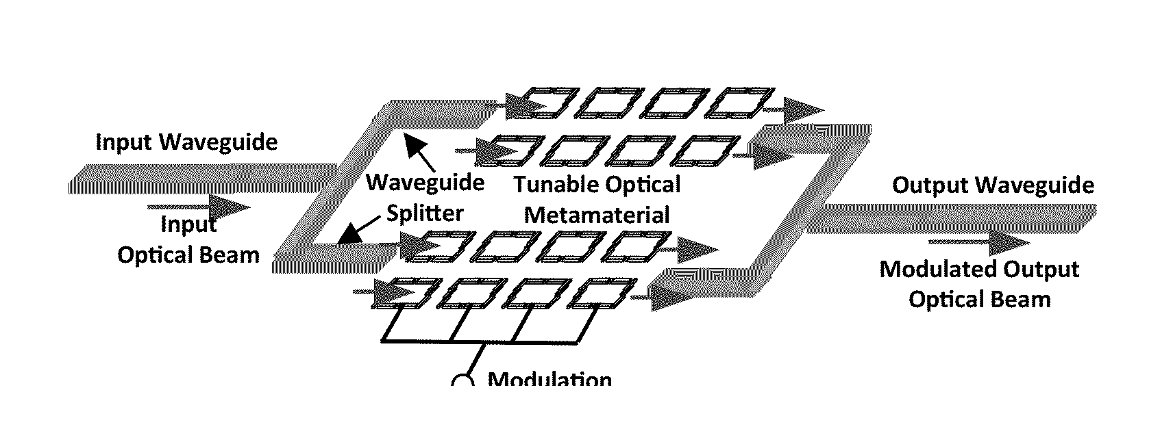
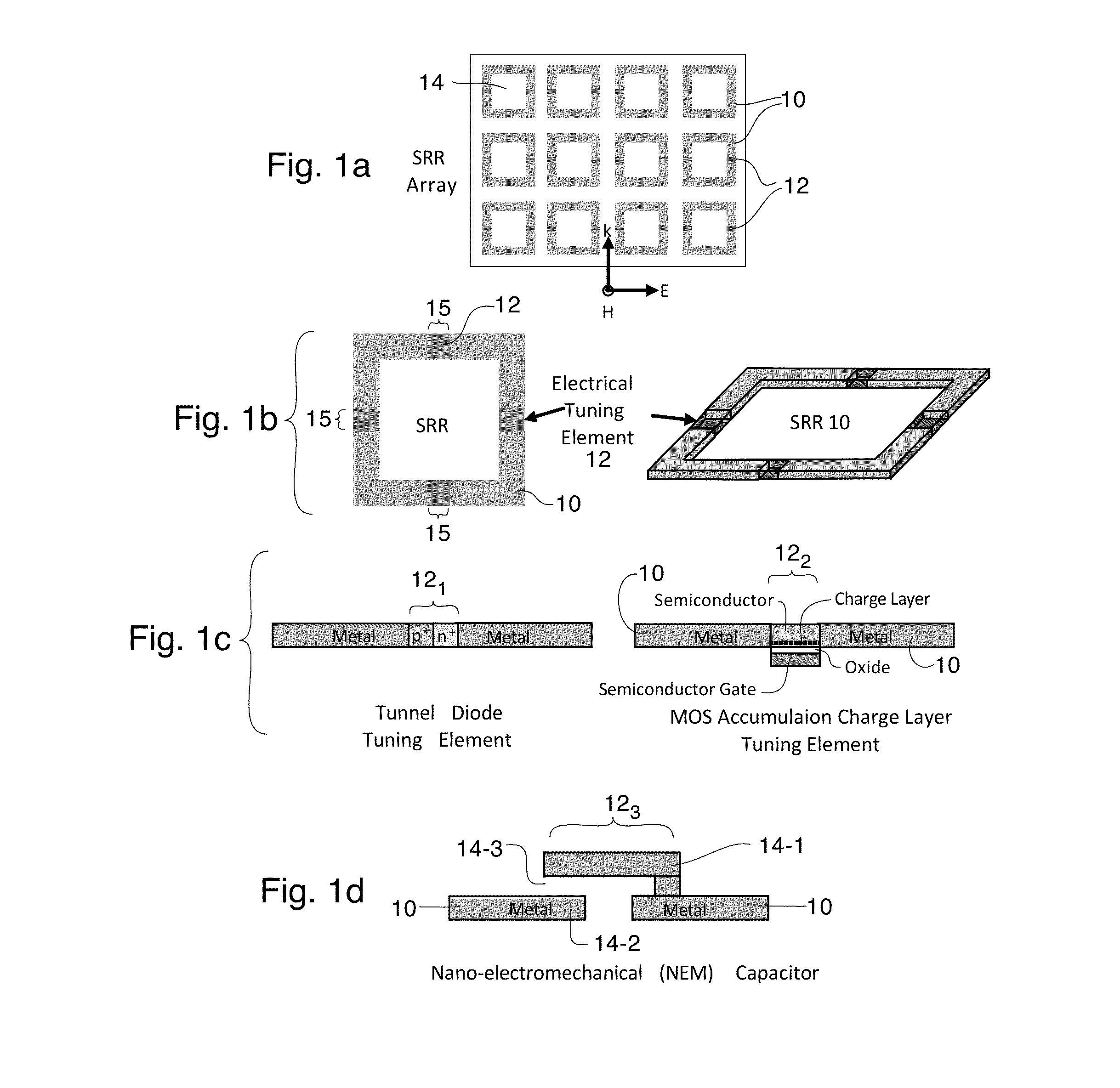
[0022]The tunable optical metamaterial is composed of a two-dimensional array of sub-wavelength-scale resonant metallic structures 10 with integrated nano-scale voltage-controllable electrical tuning elements 12 disposed in the sides thereof in an exemplary embodiment as shown in FIG. 1a. The metallic unit-cell structures 10 are preferably disposed on a dielectric substrate 20 for support and are designed to have electrical resonances preferably at optical frequencies (i.e. electromagnetic radiation having a wavelength longer than 0.4 microns (blue / violet end of the visible spectrum) and shorter than 0.3 mm (1 terahertz frequency)), which can be achieved by reducing their dimensions to sub-micron scales. If the metallic unit-cell structures 10 are to be used at lower optical frequencies (such infrared, terahertz), then their sizes may be increased accordingly.

[0023]There are a number of metallic structures 10 that have electrical resonances at optical frequencies such as metallic sp...


PUM

PropertyMeasurementUnit
wavelengthaaaaaaaaaa
temperaturesaaaaaaaaaa

Abstract

A tunable metamaterial has a two dimensional array of resonant annular ring elements; and a plurality of voltage controllable electrical tuning elements disposed in or adjacent openings in each of said ring elements, each of said voltage controllable electrical tuning element ohmically contacting portions of only one of said ring elements. The voltage controllable electrical tuning elements may comprise highly doped semiconductor tunnel diodes, or the charge accumulation layer at the semiconductor/insulator interface of a metal-insulator-semiconductor structure, or nanoelectromechanical (NEMs) capacitors. The tunable metamaterial may be used, for example, in an optical beam steering device using the aforementioned tunable optical metamaterial in which a free-space optical beam is coupled into a receiving portion of a plane of the optical metamaterial and is steered out of a transmitter portion of the plane of the optical metamaterial in controllable azimuthal and elevational directions. The tunable metamaterial additionally has other applications.

Description

Cross Reference to Related Applications[0001]NoneTECHNICAL FIELD[0002]This invention is about a tunable optical metamaterial whose effective refractive index can be spatially programmed, in two dimensions, resulting in an artificial material with a tunable index profile. The disclosed metamaterial can be used in a number of applications, including optical beam steering, optical modulation, and optical beam shaping.BACKGROUND[0003]Optical beam steerers are known in the prior art. A liquid crystal-based optical phased array (LC-OPA) may be the current the state-of-the-art in optical beam steering devices. See P. F. McManamon et. al., Proceedings of IEEE, Vol. 40, No. 2 (1996) p. 268. It consists of a liquid crystal (LC) cell with one-dimensional patterned transparent conductor strips in which each strip defines an element of the linear array. For beam steering in the two azimuthal and elevational directions, two such LC cells are arranged in orthogonal orientations.[0004]LC-OPA is a f...

Claims


Application Information

Patent Timeline
Patent Type & Authority Applications(United States)
IPC IPC(8): G02F1/29H01L31/0216
CPCH01L31/02161G02F1/29B82Y20/00B82Y40/00G01S7/4817G02B1/002G02F1/0018G02F1/218G02F1/2257G02F1/292G02F2202/30G02F2203/12G02F2203/13G02F2203/15G02F2203/24G01S17/34G02F1/0151G02F1/212G02F1/291H01P7/082H01P7/088H01Q15/002H01Q15/0086G02F1/0316H01L21/84H01L29/66151H04B10/615
Inventor SAYYAH, KEYVANSCHAFFNER, JAMES H.PATTERSON, PAMELA R.
Owner HRL LAB
Why Eureka
Try Eureka