Dynamic mixing and electroporation chamber and system

a technology of electroporation chamber and electroporation chamber, which is applied in the direction of specific use bioreactor/fermenter, enzymology, after-treatment of biomass, etc., can solve the problems of reducing the efficiency of transfection, degrading the polynucleotide, and increasing the volume of cells transfected in increments, so as to achieve enhanced mixing

Active Publication Date: 2014-08-07
CELLECTIS SA
View PDF7 Cites 7 Cited by
  • Summary
  • Abstract
  • Description
  • Claims
  • Application Information

AI Technical Summary

Benefits of technology

[0029]Mixing continues to occur after the two water-based liquids flow down the side of the chamber when they enter the water-based liquid mixture in the bottom of the chamber. Mixing is enhanced by re-directing the water-based liquid with minimal turbulence by a curved section at the bottom of the same side of the chamber where water-based liquids enter the chamber. Mixing further continues when the two water-based liquids are further re-directed by a second curved corner at the bottom of the chamber.

Problems solved by technology

Due to limitations on maximum electrical current inherent in commercial electroporators, transfection of large volumes of cells must be done in increments.
In either case, one limitation is that if cells and polynucleotides are all mixed at the beginning of the process, nucleases that occasionally contaminate cell suspensions can degrade the polynucleotides and reduce transfection efficiency.
This problem becomes worse as the cell density increases because cell associated nucleases will increase in concentration as the cell density increases.
However, most known mixing processes require turbulence created by baffles, rotors, jets or other means that create extreme shearing forces to effect rapid mixing.

Method used


Image

  • Dynamic mixing and electroporation chamber and system
  • Dynamic mixing and electroporation chamber and system
  • Dynamic mixing and electroporation chamber and system

Examples


example 1

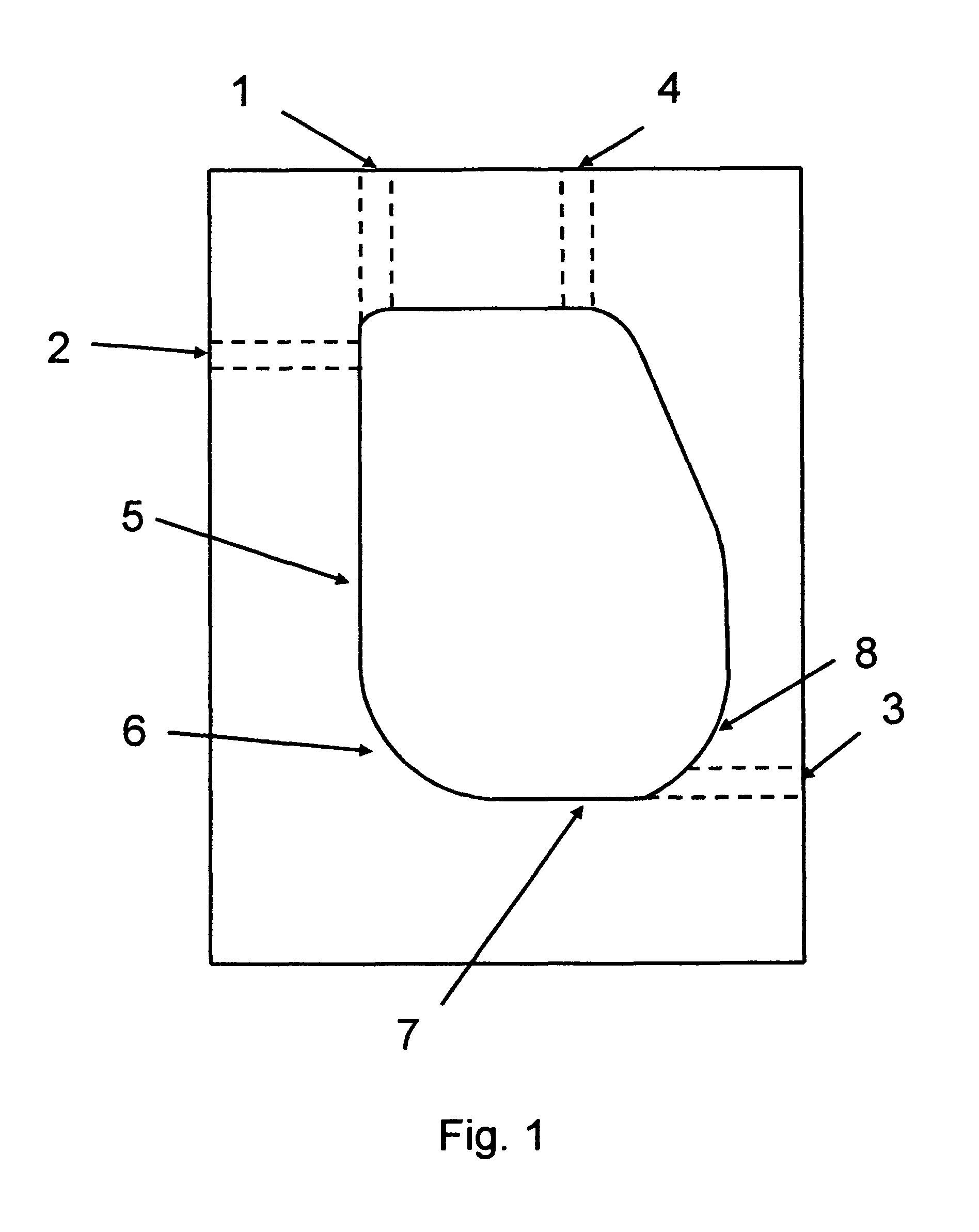
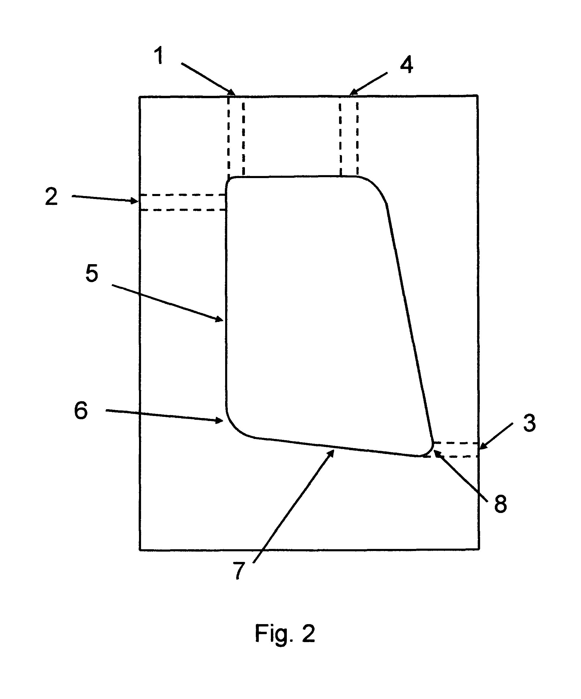
[0123]Demonstration of water-based liquid mixing in chamber. See Table 1 below. Efficiency of water-based liquid mixing in various chamber shapes was evaluated using water-based liquids with pH sensitive dyes. In this experiment, placement of inlet orifices on the same or opposite sides was evaluated. Water-based liquid A was prepared as follows: Glacial acetic acid (4.5 ml) was mixed with 1.5 L water. Thymol blue dye (150 mg) was dissolved in 15 ml DMSO. The dye and acid water-based liquids were then mixed. Sephadex G25 (20 gm / 250 ml water-based liquid) was mixed into the acid-dye water-based liquid to simulate cell density. Water-based liquid B was prepared as follows: Sodium hydroxide (4 gm) was added to 96 ml water. The original color of water-based liquid A was orange. The original color of water-based liquid B was clear. The color of the two water-based liquids mixed at a ratio of 5 ml water-based liquid A to 0.75 ml water-based liquid B was blue.

[0124]Watson-Marlow peristalti...

example 2

[0128]Demonstration that RNAse contamination impairs expression of mRNA delivered using electroporation unless electroporation pulses are delivered before RNA degradation. See FIG. 6, circular points for after 60 seconds after mixing. VERO cells were grown to confluence in T150 tissue culture flasks. The cells were harvested using cell culture grade trypsin. Cells were mixed with complete growth medium and washed 2 times in Cytoporation Medium T-4 (Cyto Pulse Sciences, Inc.). This electroporation medium is RNAse free. The cells were re-suspended in Cytoporation Medium T-4 at a cell density of one million cells / ml. Cells were divided into 2 groups. In one group contamination of RNAse was simulated by adding 50 units / ml RNAse I. No RNAse was added to the other cell suspension. Messenger RNA capable of expressing green fluorescent protein (GFP) was added at a concentration of 40 μg / ml at various times prior to electroporating the cells in 4 mm gap electroporation cuvettes. The electrop...

example 3

[0130]Demonstration that RNAse contamination impairs expression of mRNA delivered using electroporation unless electroporation pulses are delivered before RNA degradation—evaluation at shorter time intervals. See FIG. 6, circular points prior to 60 seconds after mixing. VERO cells were grown to confluence in T150 tissue culture flasks. The cells were harvested using cell culture grade trypsin. Cells were mixed with complete growth medium and washed 2 times in Cytoporation Medium T-4 (Cyto Pulse Sciences, Inc.). This electroporation medium is RNAse free. The cells were re-suspended in Cytoporation Medium T-4 at a cell density of two million cells / ml. Cells were divided into 2 groups. In one group contamination of RNAse was simulated by adding 50 units / ml RNAse I. No RNAse was added to the other cell suspension. See FIG. 6, rectangular shaped points. Messenger RNA capable of expressing green fluorescent protein (GFP) was added at a concentration of 40 μg / ml at various times prior to e...


PUM

PropertyMeasurementUnit
volumesaaaaaaaaaa
volumesaaaaaaaaaa
volumesaaaaaaaaaa

Abstract

The present invention relates to an apparatus for mixing cells and exogenous material for delivery of the exogenous material into cells using electroporation in a manner that preserves cell viability and integrity of the exogenous material. The exogenous material can be polynucleotides, peptides, proteins or other pharmaceutical molecules. It further provides a chamber that can be used to electroporate the contents of the chamber after mixing. In accordance with the invention, cell suspensions that may be contaminated with degrading enzymes are stored separately from water-based liquids that contain the exogenous material. Contact of the two water-based liquids (cell suspension and exogenous material) first occurs within the chamber. The chamber of the present invention has two or more inlet ports to allow separate entrance of water-based liquids. Two other ports are vent and exit ports. The inside of the chamber allows flow of all water-based liquids down the same side of the chamber and curved corners for redirecting flow direction and gently mixing water-based liquids. The chamber also includes electrodes as chamber walls for electroporation of chamber contents.

Description

CROSS-REFERENCE TO RELATED APPLICATION[0001]This application claims priority based upon copending U.S. Provisional Patent Application of King, Walters, Deitz, Rodis, and Walters, Ser. No. 61 / 395,267, Filing Date 12 May 2010, for DYNAMIC MIXING AND ELECTROPORATION CHAMBER AND SYSTEM.BACKGROUND OF THE INVENTION[0002]1. Technical Field[0003]The present invention is in the technical field of an apparatus for large scale electroporation.[0004]2. Background Art[0005]Delivering large molecules into living cells for therapeutic purposes, using ex vivo or in vitro electroporation, has been described in the literature for many years. Electroporation enhances the movement of molecules into and out of living cells or non-living vesicles. The practical uses are many and vary according to the complexity of material delivered, the site of delivery, and the purpose for delivery. Complexity of material delivered ranges from small drug molecules that are otherwise difficult to get into cells to compl...

Claims


Application Information

Patent Timeline
Patent Type & Authority Applications(United States)
IPC IPC(8): C12N13/00
CPCC12N13/00C12M35/02
Inventor KING, ALAN D.WALTERS, RICHARD EDEITZ, STEPHEN BRODIS, JR., DONALD JWALTERS, DERIN C
Owner CELLECTIS SA
Why Eureka
Try Eureka