Supercharge Your Innovation With Domain-Expert AI Agents!

Methods and apparatus for cleaning flip chip assemblies

a technology of flip chip and assembly, which is applied in the direction of cleaning equipment, chemistry apparatus and processes, cleaning using liquids, etc., can solve the problems of difficult to remove charred and caramelized flux residues, complex cleaning of flip chip assemblies, and difficult to clean conventional surfaces, etc., to increase the rotation speed and increase the centrifugal force. , the effect of increasing the rotation speed of the chuck assembly

Inactive Publication Date: 2014-08-14
ACM RES SHANGHAI
View PDF6 Cites 9 Cited by
  • Summary
  • Abstract
  • Description
  • Claims
  • Application Information

AI Technical Summary

Benefits of technology

The invention relates to an apparatus for cleaning flip chip assemblies. The apparatus includes a tank for holding cleaning solution, a liquid circulation loop with a pump, and at least four outflow ports for reclaiming the cleaning solution. There is also an ultrasonic / megasonic device for agitation during the cleaning process. The apparatus allows for a high cleaning performance by pre-soaking the flip chips for a long time using a low rotation speed, followed by a high-speed rotation to remove contaminants using the centrifugal force. The method may be repeated for improved cleaning performance.

Problems solved by technology

Cleaning flip chip assemblies is more complex than cleaning conventional surface mount or through-hole electronic assemblies.
To meet performance and dependability standards, flip-chip assemblies must be free of contamination, such as flux, finger soils, water, or other surface contaminants, otherwise such residue left will lead to ionic contamination and corrosion, and interfere with underfilling to create voids that promote moisture collection, overheating and part failure.
However, there are two significant problems for thoroughly removing the residues: (1) high-temperature during reflow soldering process will create charred and caramelized flux residues that are difficult to be removed; (2) as shrinkage of the bump dimension and pitch continues, the bump structure becomes more fragile and the gap between the bumps and the substrates becomes much smaller, the small and fragile bumps interconnect structure of flip chip assemblies only permits a very narrow space between the chip bond pads to be cleaned, such small gap makes thorough and consistent cleaning of flip chip assemblies a big challenge.

Method used


Image

  • Methods and apparatus for cleaning flip chip assemblies
  • Methods and apparatus for cleaning flip chip assemblies
  • Methods and apparatus for cleaning flip chip assemblies

Examples


Embodiment Construction

[0040]Preferred embodiments of this invention will be described in detail hereinafter with reference to the drawings. The embodiments of the present invention described are not limit the invention to the precise forms disclosed in the following detailed description.

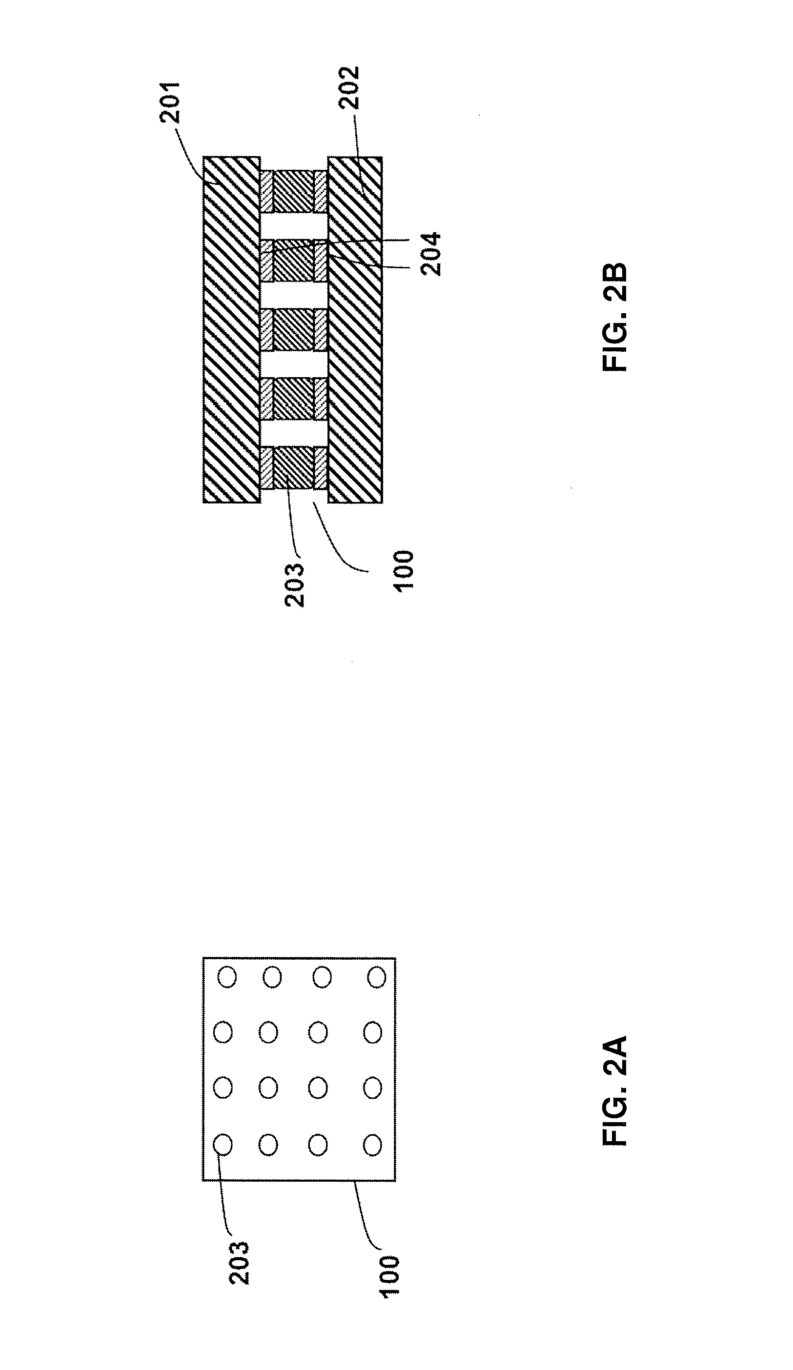
[0041]FIGS. 2a-2b show top section view and cross-sectional view of a flip chip assembly 100 of a known type, respectively. In some case, the illustrative structure represented in FIGS. 2a-2b is just a part of a flip chip assembly. As depicted, chip 100 including two chip bond pads 201 and 202, which are coupled face-down to each other by an array of solder balls 203. The shape of the pads can be square, rectangular, circular or other shapes depending on specific purpose. During soldering, there will be flux residue or other contaminants 204 that remain on the surface of the solder balls 203 and the surface of the bonding pads 201 and 202. These residues must be cleaned sufficiently, or else it will be left as inclusion i...


PUM


Abstract

An apparatus for cleaning flip chip assemblies is provided. The apparatus comprises: a chuck assembly; a motor coupled to the chuck assembly by a spindle; at least one carrier for holding flip chips; at least one spray nozzle for directing DIW, a cleaning solution, a gas or a vapor. Apparatus of the invention further provides a method for cleaning flip chip assemblies. The method comprises: loading at least one flip chip to the flip chip carriers; rotating the chuck assembly at a rotation speed; flowing DIW for rinsing the flip chips; flowing a cleaning solution for removing the contaminants; applying ultrasonic / megasonic energy to the flip chips; blowing a gas or a vapor via the spray nozzles for drying the flip chips; bringing the flip chips out of the flip chip carriers.

Description

FIELD OF THE INVENTION[0001]The present invention generally relates to an apparatus and a method for cleaning flip chip assemblies. More particularly, it relates to an apparatus and a method for removing flux residues and other contaminants from flip chips.BACKGROUND[0002]So-called flip chip assembly is the direct electrical connection of face-down electronic components onto substrates, circuit boards or other carriers, by means of conductive bumps on the chip bond pads. The bumps typically range in diameters from 30-200 microns although larger and smaller sizes are available, and are generally spherical or nearly spherical in shape. Cleaning flip chip assemblies is more complex than cleaning conventional surface mount or through-hole electronic assemblies. In the fabrication of flip chip assemblies, fluxes are frequently employed to join electronic components in soldering process. Various types of fluxes, such as rosin-based fluxes, halogens contained fluxes, are used in this proce...

Claims


Application Information

Patent Timeline
Patent Type & Authority Applications(United States)
IPC IPC(8): H01L21/67H01L21/02
CPCH01L21/67051H01L21/67023H01L21/02052H01L24/16H01L24/75H01L24/81H01L2224/7501H01L2224/81911H01L2224/131H01L2224/16227H01L2224/16225H01L2924/014
Inventor ZHANG, XIAOYANCHEN, FUPINGWANG, HUI
Owner ACM RES SHANGHAI
Features
  • R&D
  • Intellectual Property
  • Life Sciences
  • Materials
  • Tech Scout
  • Unparalleled Data Quality
  • Higher Quality Content
  • 60% Fewer Hallucinations
Learn More