Test strip, detecting device and detecting method

a test strip and detecting device technology, applied in the field of test strips, can solve the problems of difficult to supply blood to the heart, brain, liver and kidney, difficult to clean the capillary viscometer, and not convenient to carry the capillary viscometer with the patient, so as to reduce the exposure to reaction reagents, increase the capture of signals, and accurate detect the concentration of analyte

Active Publication Date: 2014-08-14
HMD BIOMEDICAL
View PDF6 Cites 10 Cited by
  • Summary
  • Abstract
  • Description
  • Claims
  • Application Information

AI Technical Summary

Benefits of technology

[0012]It is an object of the present invention to provide a test strip and a detecting device to detect a specimen for not only detecting the flow time and the concentration of the analyte of the specimen, but also correcting the concentration of the analyte by using the flow time to accurately detect the concentration of the analyte. In order to avoid affecting the flow characters of the specimen itself, it increases the capture of signals by enhancing the voltage, and sets the working electrode as the electrode that used to detect the flow time at the same time; therefore, the sample path can reduce exposure to reaction reagents to enhance the accuracy of the flow time. In order to achieve the above object, the present invention provides a test device comprising: a test strip and an electrochemical instrument. The test strip includes a first specimen path, a first electrode set, a second specimen path, a second electrode set and a reaction reagent, wherein the first sample path is connected in series with the second sample path. The first specimen path includes an inlet end; the first electrode set has at least a portion thereof disposed in the first specimen path, and the first electrode set at least includes a first electrode and a first reference electrode. The second specimen path includes a discharge end; the second electrode set is disposed in the second specimen path, and the second electrode set has at least a working electrode and a second reference electrode. Wherein, a first impulse signal is generated when the specimen is in contact with the first electrode and the first reference electrode, and a second impulse signal is generated when the specimen is in contact with the first reference electrode and the working electrode, thereby obtaining a flow time of the specimen according to the first impulse signal and the second impulse signal. The reaction reagent is disposed in the second specimen path, and the reaction reagent at least includes an enzyme for detecting a concentration of the analyte of the specimen. The electrochemical instrument is electrically connected to the test strip for obtaining the flow time and the concentration of the analyte, and then the flow time can be used to correct the concentration of the analyte.
[0013]It is another object of the present invention to provide a detecting method for detecting a specimen; the detecting method is used to detect the flow time of the specimen and a concentration of the analyte, and to correct the concentration of the analyte by the flow time to accurately detect the concentration of the analyte. In order to avoid affecting the flow characters of the specimen itself, it increases the capture of signals by enhancing the voltage, and sets the working electrode as the electrode that used to detect the flow time at the same time; therefore, the sample path can reduce exposure to reaction reagents to enhance the accuracy of the flow time. In order to achieve the above object, the present invention provides a detecting method using an electrochemical instrument to detect a specimen, the detecting method comprising the following steps: providing the test strip; providing a first voltage to the first electrode, and providing a second voltage to the working electrode; receiving the specimen in the first specimen path and the second specimen path; recording a first impulse signal generated when the specimen is in contact with the first electrode and the first reference electrode, and recording a second impulse signal generated when the specimen is in contact with the first reference electrode and the working electrode; using the first impulse signal and the second impulse signal to obtain a flow time of the specimen; providing a reaction voltage to the working electrode; enabling an electrochemical reaction between the reaction reagent and the analyte of the specimen; using the electrochemical reaction to calculate an uncorrected concentration of the analyte; and using the flow time to correct the uncorrected concentration of the analyte.

Problems solved by technology

Furthermore, when the blood viscosity increases, there will be more resistance in the blood, making it difficult to supply blood to the heart, brain, liver and kidney.
Besides, the capillary viscometer has large equipment size, it needs a lot of sample volume to process and tends to require long reaction time; therefore, it is not easy to clean the capillary viscometers, and it is not convenient to carry the capillary viscometer with the patient to detect the blood viscosity in real time.
When it is necessary to obtain blood viscosity data from a group of people, it takes a great amount of time in detecting blood viscosity from each one of them and it requires getting enough specimens from them; therefore, it is inefficient and also not cost-effective.
Generally an electrochemical sensor provides a voltage no higher than 0.5V to save power and to avoid triggering unnecessary reactions; however, the signal could be very weak and unstable between the liquid sample such as blood and the electrodes, it could be covered by background noises and is difficult to be detected.
In other words, the reaction of the enzyme and the detection of the flow time happen in the same channel and could easily interfere with each other; besides, the enzyme disposed on the electrode set also comprises mixtures such as polymeric binders, stabilizers, buffers, surfactants, which could cause the fluidity of the liquid sample to change and often lead to differences in flow time detection.
Besides, since the enzyme is provided for reacting with the analyte of the liquid sample to detect the flow time, the flow time signal will not be obtained until the blood samples reacted with the enzyme, otherwise a weak signal or a delayed signal will be detected.
Therefore, the prior art technique cannot provide stable detection results and often fails to reproduce itself.
When performing the fluidity detection, it is necessary to wait for blood glucose to react with enzymes to generate a detectable signal, however, by that time the blood may has already flowed through the electrode, so the generated signal does not reflect the real fluidity.
As shown in FIG. 1A of this patent, it is clear that when the hematocrit increases, the fill time values tend to scatter, which implies that the patent does not do well in reproducing itself.
A diabetic often suffers from other complications such as high blood pressure, anemia or other heart disease, so the hematocrit of the diabetic could easily become abnormal.
Since the prior art techniques cannot precisely obtain blood viscosity within a short amount of measurement time.

Method used


Image

  • Test strip, detecting device and detecting method
  • Test strip, detecting device and detecting method
  • Test strip, detecting device and detecting method

Examples


Embodiment Construction

[0018]The advantages and innovative features of the invention will become more apparent from the following detailed description when taken in conjunction with the accompanying drawings.

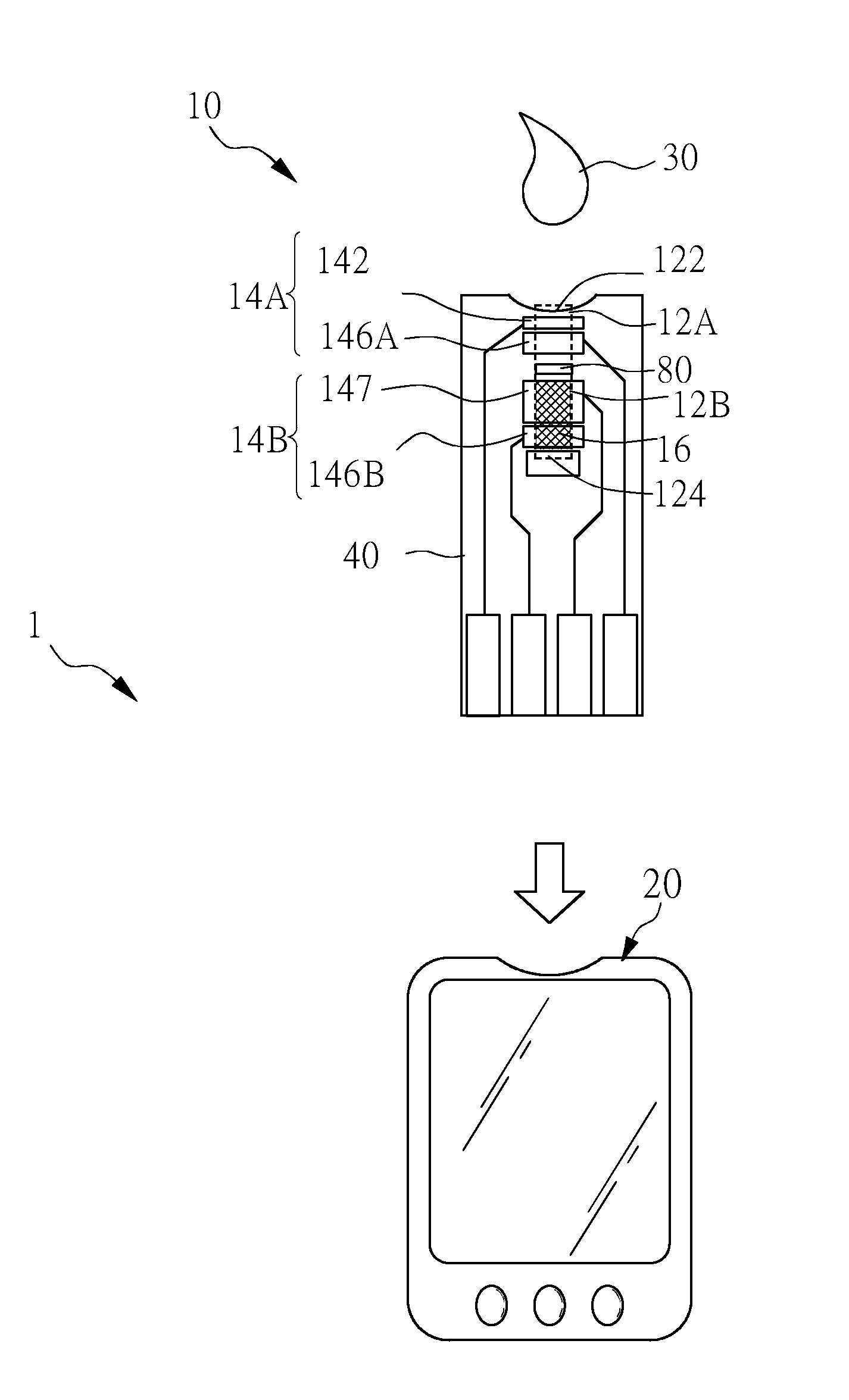
[0019]The present invention provides a detecting device for detecting a specimen, wherein the detecting device detects the flow time of the specimen and the concentration of the analyte for using the flow time to correct the concentration of the analyte. In an embodiment of the present invention, the detecting device can be used as a blood glucose detecting device.

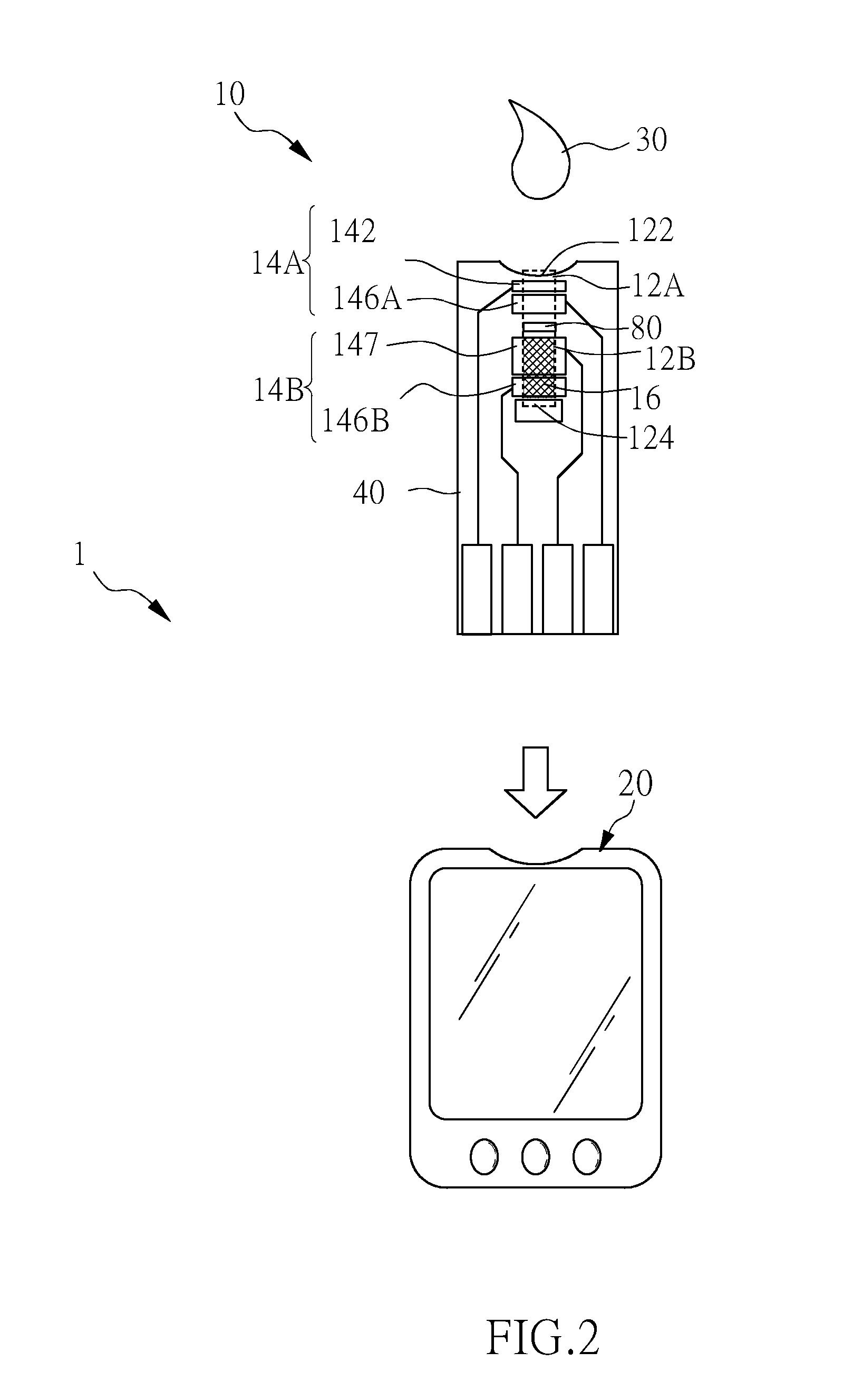
[0020]Please refer to FIG. 2 to FIG. 2B for the detecting device of the present invention.FIG. 2 illustrates a view of using the detecting device to detect according to an embodiment of the present invention; FIG. 3A to FIG. 12B illustrate various structures of the test strip of the detecting device according to an embodiment of the present invention.

[0021]First, please refer to FIG. 2, according to an embodiment of the present invention, th...


PUM

PropertyMeasurementUnit
voltageaaaaaaaaaa
diameteraaaaaaaaaa
voltageaaaaaaaaaa

Abstract

A test strip, a detecting device, and a detecting method are disclosed. The test strip includes a first specimen path, a first electrode set, a second specimen path, a second electrode set, and a reaction reagent. When the specimen contacts the first electrode set and the second electrode set, a first pulse signal and a second pulse signal are generated for obtaining a flow time of the specimen. When the specimen contacts the reaction reagent, the analyte concentration of the specimen can be obtained, and the concentration of the analyte can be corrected by the flow time.

Description

BACKGROUND OF THE INVENTION[0001]1. Field of the Invention[0002]The present invention relates to a test strip, a detecting device, and a detecting method, and more particularly, to a test strip, a detecting device, and a detecting method used to obtain a flow time of a specimen and use the flow time to correct a concentration of the analyte of the specimen.[0003]2. Description of the Related Art[0004]Electrochemical bio-sensors have been widely adopted to find out the concentration of the analyte in a liquid specimen, such as blood or urine. There are many kinds of electrochemical bio-sensors, such as blood glucose sensors, cholesterol sensors, uric acid biosensors, and lactic acid biosensors. In particular, blood glucose sensors have become indispensable for diabetics. Generally, a blood glucose sensor is formed in a strip shape and comprises at least two electrodes such as a working electrode and a reference electrode for receiving electrical signals proportional to the concentrat...

Claims


Application Information

Patent Timeline
Patent Type & Authority Applications(United States)
IPC IPC(8): C12Q1/00
CPCC12Q1/001G01N27/3272G01N27/3274
Inventor HSU, TIEN-TSAI
Owner HMD BIOMEDICAL
Why Eureka
Try Eureka