

Deposition substrate and scintillator panel
a technology of substrate and scintillator, which is applied in the direction of optical radiation measurement, fluorescence/phosphorescence, instruments, etc., can solve the problems of unfavorable image quality comparison with the quality level of screen film system images, less sharp cr x-ray images, and insufficient spatial resolution, etc., to achieve excellent cuttability, excellent sensitivity and sharpness, excellent effect of cutting
- Summary
- Abstract
- Description
- Claims
- Application Information
AI Technical Summary
Benefits of technology
Problems solved by technology
Method used
Image

Examples
example 1
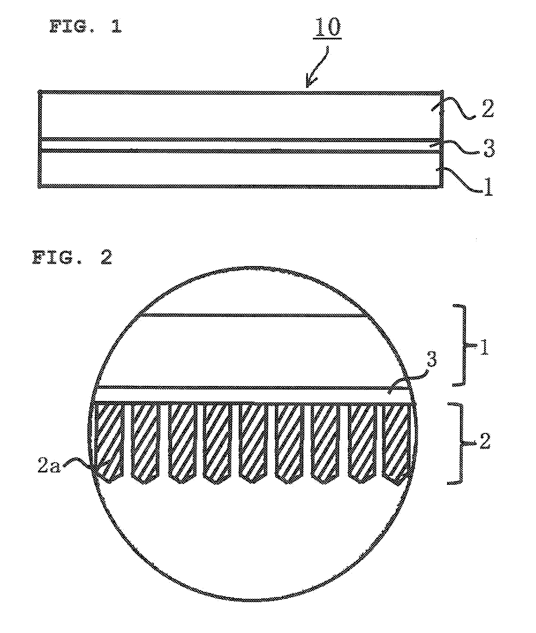
Deposition Substrate No. 1
[0414]40 Parts by mass in total of rutile-form titanium dioxide (CR93 manufactured by ISHIHARA SANGYO KAISHA, LTD., average particle diameter 0.28 μm) as light-scattering particles and a polyester resin (VYLON 550 manufactured by TOYOBO CO., LTD., Tg: −15° C.) as a binder resin, and 30 parts by mass of cyclohexanone and 30 parts by mass of methyl ethyl ketone (MEK) as solvents were mixed together. The mixture was dispersed with a sand mill to give a first resin coating liquid (a reflective coating liquid 1). The light-scattering particles and the binder resin were used in a solid content ratio (vol %) of 20 / 80. The first resin coating liquid was applied onto a 500 mm wide polyimide film support (UPILEX S manufactured by UBE INDUSTRIES, LTD., 125 μm thick) with a comma coater. The first resin coating liquid was then dried at 180° C. for 3 minutes to form a resin layer on the support. Thus, a deposition substrate No. 1 was fabricated which included the suppor...
example 7
Fabrication of Deposition Substrate No. 10
[0417]A deposition substrate No. 10 with the thickness described in Table 5 was fabricated in the same manner as in EXAMPLE 2, except that the type of light-scattering particles in EXAMPLE 2 was changed to hollow particles (SX866 manufactured by JSR Corporation, average particle diameter 0.3 μm).
example 8
Fabrication of Deposition Substrate No. 11
[0418]A deposition substrate No. 11 with the thickness described in Table 5 was fabricated in the same manner as in EXAMPLE 2, except that the light-scattering particles / binder resin ratio in EXAMPLE 2 was changed as described in Table 5.
PUM
| Property | Measurement | Unit |
|---|---|---|
| glass transition temperature | aaaaa | aaaaa |
| thickness | aaaaa | aaaaa |
| glass transition temperature | aaaaa | aaaaa |
Abstract
Description
Claims
Application Information