Thermomechanical processing of high strength non-magnetic corrosion resistant material

a non-magnetic corrosion resistant material and thermomechanical technology, applied in manufacturing tools, forging/pressing/hammering apparatus, etc., can solve the problems of metal alloy parts used in chemical processing facilities that may be in contact with highly corrosive and/or erosive compounds, metal alloy parts that are subject to high stress, and promote corrosion and erosion

Active Publication Date: 2014-09-11
ATI PROPERTIES LLC
View PDF13 Cites 21 Cited by
  • Summary
  • Abstract
  • Description
  • Claims
  • Application Information

AI Technical Summary

Benefits of technology

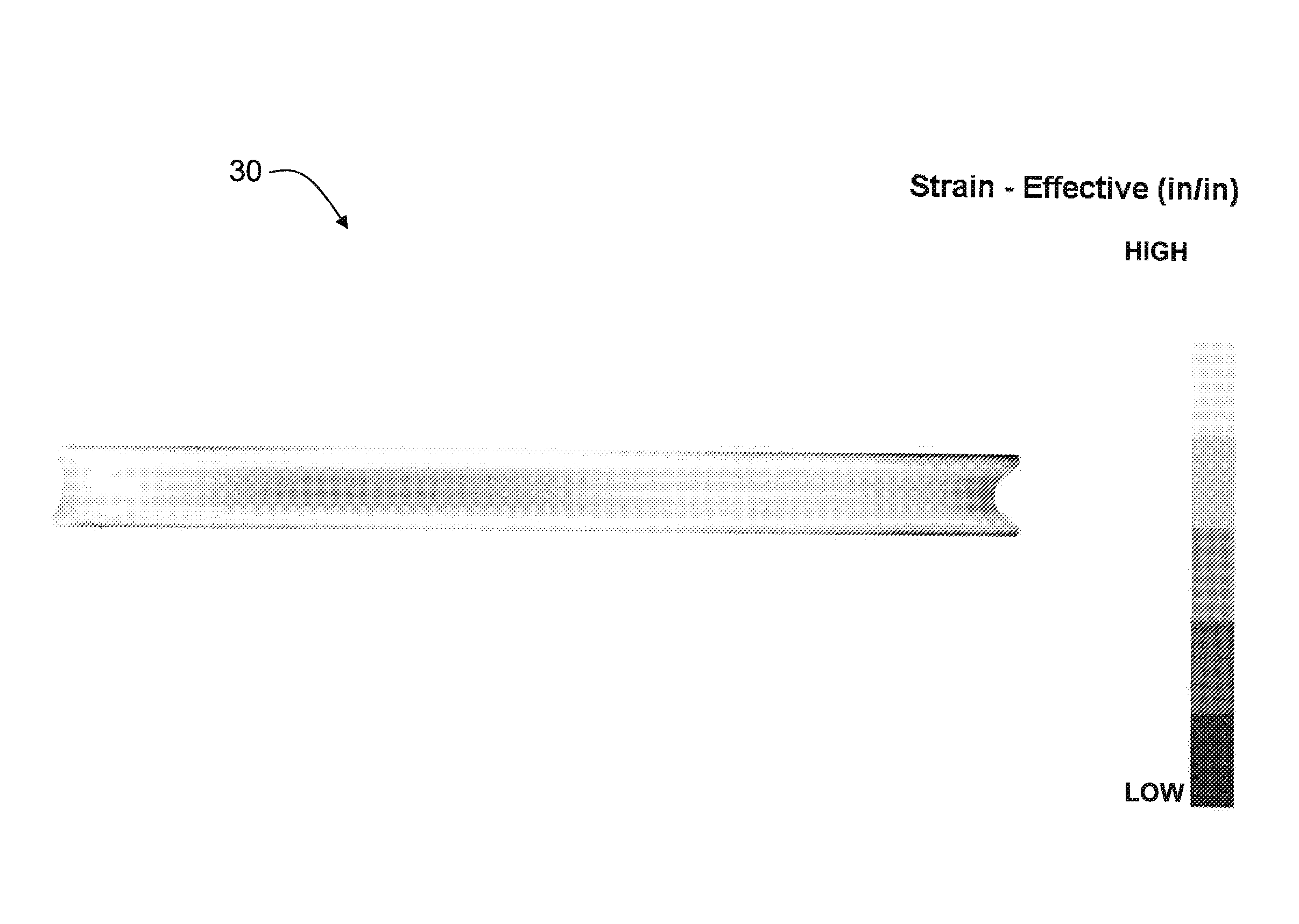
[0013]In certain non-limiting embodiments of a method according to the present disclosure, after the steps of open die press forging and radial forging, the central region strain and the surface region strain are each in a final range of from 0.3 inch / inch up to 1.0 inch / inch, with a difference in strain from the central region to the surface region of not more than 0.5 inch / inch. In a certain non-limiting embodiment of a method according to the present disclosure, after the steps of open die press forging and radial forging, the central region strain and the surface region strain are each in a final range of from 0.3 inch / inch to 0.8 inch / inch. In other non-limiting embodiments, after the steps of open die press forging and radial forging, the surface region strain is substantially equivalent to the central region strain and the workpiece exhibits at least one substantially uniform mechanical property throughout the workpiece cross-section.
[0014]According to another aspect of the present disclosure, certain non-limiting embodiments of a method of processing a non-magnetic austenitic stainless steel alloy workpiece comprise: heating the workpiece to a temperature in the range of from 950° F. to 1150° F.; open die press forging the workpiece to impart a final strain in the range of from 0.3 inch / inch up to 1.0 inch / inch to a central region of the workpiece; and radial forging the workpiece to impart a final strain in the range of from 0.3 inch / inch up to 1.0 inch / inch to a surface region of the workpiece, with a difference in strain from the central region to the surface region of not more than 0.5 inch / inch. In a certain non-limiting embodiment, the method includes: open die press forging the workpiece to impart a final strain in the range of from 0.3 inch / inch to 0.8 inch / inch.

Problems solved by technology

Metal alloy parts used in chemical processing facilities may be in contact with highly corrosive and / or erosive compounds under demanding conditions.
These conditions may subject metal alloy parts to high stresses and aggressively promote corrosion and erosion, for example.
If it is necessary to replace damaged, worn, or corroded metallic parts of chemical processing equipment, it may be necessary to suspend facility operations for a period of time.
Similarly, in oil and gas drilling operations, drill string components may degrade due to mechanical, chemical, and / or environmental conditions.
The drill string components may be subject to impact, abrasion, friction, heat, wear, erosion, corrosion, and / or deposits.
Conventional alloys may suffer from one or more limitations that negatively impact their performance as drill string components.
For example, conventional materials may lack sufficient mechanical properties (for example, yield strength, tensile strength, and / or fatigue strength), possess insufficient corrosion resistance (for example, pitting resistance and / or stress corrosion cracking), or lack necessary non-magnetic properties to operate for extended periods in the down-hole environment.
Also, the properties of conventional alloys may limit the possible size and shape of the drill string components made from the alloys.
These limitations may reduce the service life of the components, complicating and increasing the cost of oil and gas drilling.
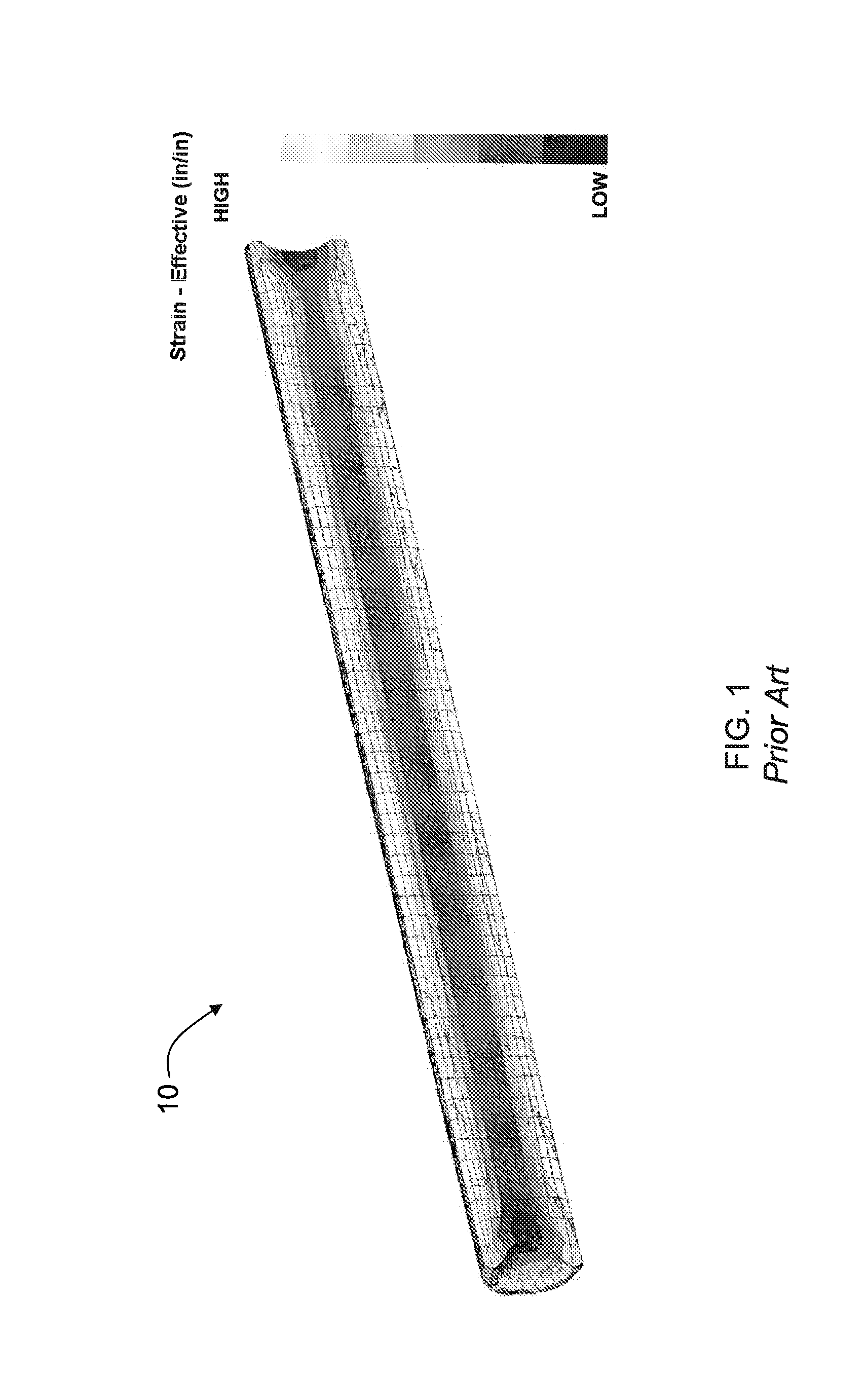
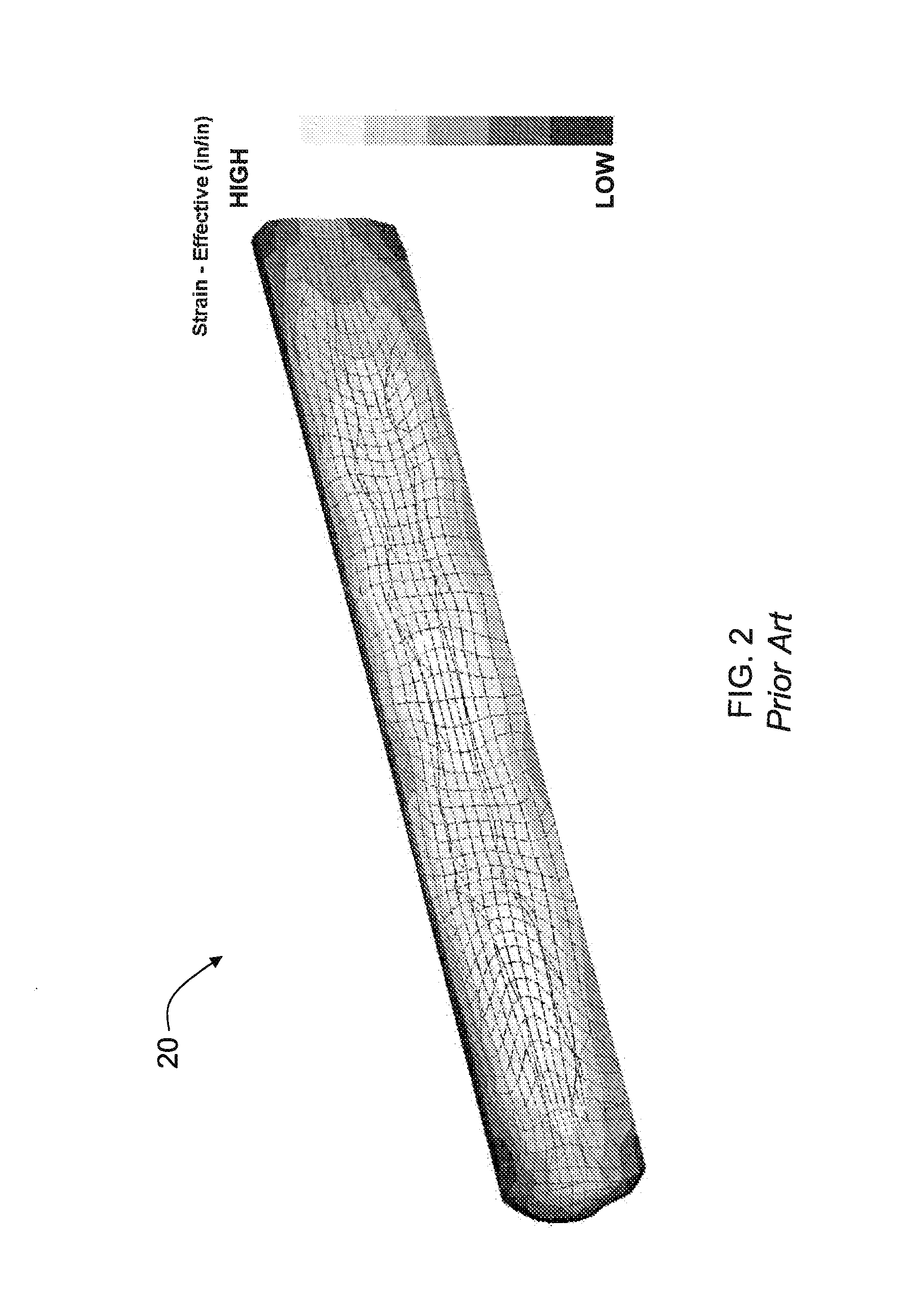
It has been discovered that during warm working radial forging of some high strength, non-magnetic materials to develop a preferred strength, there may be an uneven deformation or an uneven amount of strain in the cross-section of the workpiece.
This, however, becomes impractical with bars having finished diameters equal to or greater than 10 inches because the starting size can exceed the practical limits of ingots that can be melted without imparting problematic melt-related defects.

Method used


Image

  • Thermomechanical processing of high strength non-magnetic corrosion resistant material
  • Thermomechanical processing of high strength non-magnetic corrosion resistant material
  • Thermomechanical processing of high strength non-magnetic corrosion resistant material

Examples


example 1

[0094]FIG. 6 schematically illustrates aspects of a method 62 according to the present disclosure for processing a non-magnetic austenitic steel alloy (right side of FIG. 6) and a comparative method 60 (left side of FIG. 6). An electroslag remelted (ESR) ingot 64 having a diameter of 20 inches and having the chemistry of Heat Number 49FJ-1,2 shown in Table 2 below was prepared.

TABLE 2Element Heat 01FM-1Heat 47FJ-1, 2Heat 49FJ-2, 4C0.0140.0100.010Mn4.534.504.55Cr21.5022.2621.32Mo5.016.015.41Co2.652.602.01Fe34.1132.3739.57Nb0.0100.008Ni30.4030.0725.22W0.890.840.64N0.3650.3900.393P0.0150.0140.016S0.00020.0003Si0.300.230.30Cu1.131.221.21V0.030.040.04B0.0020.0020.002PREN16445047

[0095]The ESR ingot 64 was homogenized at 2225° F. for 48 hours, followed by ingot breakdown to about a 14-inch diameter workpiece 66 on a radial forge machine. The 14-inch diameter workpiece 66 was cut into a first workpiece 68 and a second workpiece 70 and processed as follows.

[0096]Samples of the 14-inch diamet...


PUM

PropertyMeasurementUnit
temperatureaaaaaaaaaa
diameteraaaaaaaaaa
diameteraaaaaaaaaa

Abstract

A method of processing a non-magnetic alloy workpiece comprises heating the workpiece to a warm working temperature, open die press forging the workpiece to impart a desired strain in a central region of the workpiece, and radial forging the workpiece to impart a desired strain in a surface region of the workpiece. In a non-limiting embodiment, after the steps of open die press forging and radial forging, the strain imparted in the surface region is substantially equivalent to the strain imparted in the central region. In another non-limiting embodiment, the strain imparted in the central and surface regions are in a range from 0.3 inch/inch to 1 inch/inch, and there exists no more than a 0.5 inch/inch difference in strain of the central region compared with the strain of the surface region of the workpiece. An alloy forging processed according to methods described herein also is disclosed.

Description

BACKGROUND OF THE TECHNOLOGY[0001]1. Field of the Technology[0002]The present disclosure relates to methods of processing high strength, non-magnetic corrosion resistant alloys. The present methods may find application in, for example, and without limitation, the processing of alloys for use in the chemical, mining, oil, and gas industries. The present invention also relates to alloys made by methods including the processing discussed herein.[0003]2. Description of the Background of the Technology[0004]Metal alloy parts used in chemical processing facilities may be in contact with highly corrosive and / or erosive compounds under demanding conditions. These conditions may subject metal alloy parts to high stresses and aggressively promote corrosion and erosion, for example. If it is necessary to replace damaged, worn, or corroded metallic parts of chemical processing equipment, it may be necessary to suspend facility operations for a period of time. Therefore, extending the useful ser...

Claims


Application Information

Patent Timeline
Patent Type & Authority Applications(United States)
IPC IPC(8): B21J5/02C21D8/00
CPCC21D8/005B21J5/022B21J1/02B21J1/04B21J5/08B21J7/14C21D6/004C21D7/13C22C38/001C22C38/002C22C38/02C22C38/06C22C38/42C22C38/44C22C38/46C22C38/48C22C38/50C22C38/52C22C38/54C22C38/58Y10T428/1241B21J5/02C22C38/00
Inventor FORBES JONES, ROBIN M.SMITH, JR., GEORGE J.FLODER, JASON P.THOMAS, JEAN-PHILIPPE A.MINISANDRAM, RAMESH S.
Owner ATI PROPERTIES LLC
Why Eureka
Try Eureka