
Display device

a display device and display technology, applied in the field of display devices, can solve the problems of difficult to see the spacer in the stereoscopic view, and the columnar spacer is easy to be particularly viewed, so as to reduce crosstalk and a response time, and prevent the easy to see spacers

Active Publication Date: 2014-09-18
JAPAN DISPLAY INC
View PDF4 Cites 32 Cited by
  • Summary
  • Abstract
  • Description
  • Claims
  • Application Information

AI Technical Summary

Benefits of technology

The invention provides a display device that can reduce crosstalk and have a faster response time. This is achieved by using a liquid crystal lens panel with a special arrangement of stripe electrodes and a twisted nematic mode of liquid crystal display. When the liquid crystal lens panel is not driven, a two-dimensional display can be achieved by rotating the polarized light incident on the liquid crystal material. Increasing the width of the stripe electrodes and reducing the distance between them can further reduce crosstalk and increase the response time of the liquid crystal lens panel.

Problems solved by technology

However, if the left-eye image inappropriately reaches the right eye or the right-eye image inappropriately reaches the left eye, crosstalk (double image) occurs, in which the stereoscopic view is not provided.
Furthermore, a columnar spacer is provided at the center of the lens so as not to influence the performance of the lens, which causes a problem that the columnar spacer is easily viewed particularly in the three-dimensional display.

Method used


Image

  • Display device
  • Display device
  • Display device

Examples


working example

[0079]Next, the relation of a distance d of the cell gap and the interval s of the adjacent stripe electrodes 42 will be described with reference to FIG. 4. The inventors found that in the configuration of the liquid crystal lens panel 30 shown in this example, to obtain an ideal refractive index distribution, an optimal range for s / d is present. The range is preferably 3.5≦s / d≦7, and more preferably 4.5<s / d<5.5.

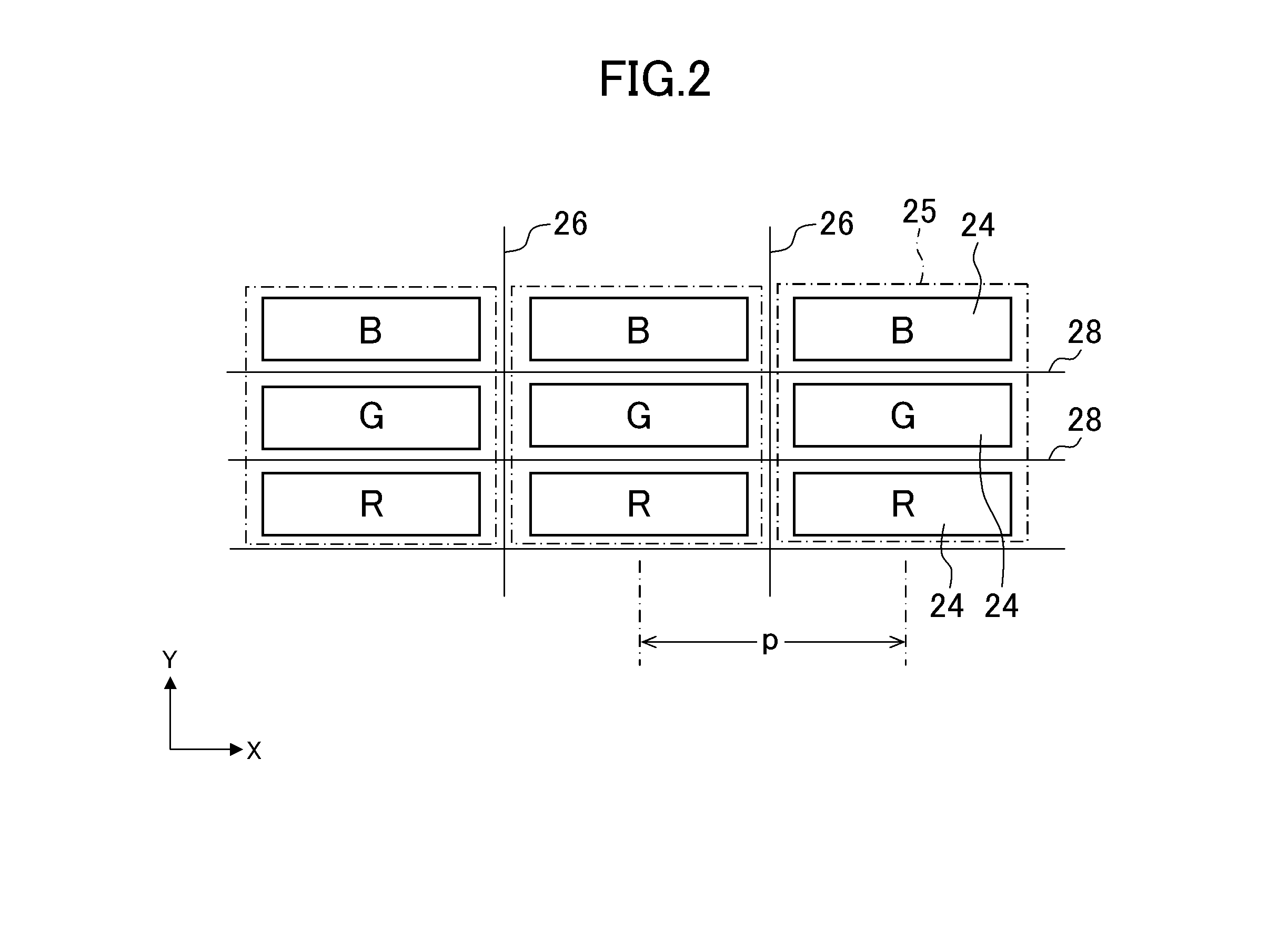
[0080]This range was calculated by calculating s / d with respect to crosstalk by simulation. The simulation was performed by calculating s / d by light beam tracing software using a calculation result of liquid crystal orientation. In the calculation, the pitch p (FIG. 2 or FIG. 6) of the pixels 24 was set to 80 μm.

[0081]FIG. 15 is a graph illustrating a simulation result. Since if crosstalk is 1% or lower, it is difficult for a human to recognize the crosstalk, it can be understood that 3.5≦s / d≦7 is preferable for reduction of the crosstalk. Further, in 4.5<s / d<5.5, the crosst...


PUM


Abstract

A liquid crystal material is driven in a twisted nematic mode so that while liquid crystal molecules lose, on a stripe electrode, rotary power toward a direction along an electric field by a voltage applied between the stripe electrode and a second electrode and form, in a region between the adjacent stripe electrodes, refractive index distribution of a lenticular lens that includes a cylindrical lens in which a cylindrical axis is arranged in a first direction. The cylindrical lens faces at least two rows of pixels, and has an effective refractive index for causing light from the at least two rows of pixels to advance in separating directions from each other after emission from a second polarizing plate. A distance d of a cell gap and an interval s between the adjacent stripe electrodes satisfy the relation of 3.5≦s / d≦7.

Description

CROSS-REFERENCE TO RELATED APPLICATION[0001]The present application claims priority from Japanese application JP2013-49077 filed on Mar. 12, 2013, the content of which is hereby incorporated by reference into this application.BACKGROUND OF THE INVENTION[0002]1. Field of the Invention[0003]The present invention relates to a display device.[0004]2. Description of the Related Art[0005]As a naked-eye stereoscopic display in which a two-dimensional display and a three-dimensional display are switched, a liquid crystal lens type has been proposed (JP 2010-224191A). The liquid crystal lens type that uses refractive index distribution generated by orientation distribution of liquid crystal has a characteristic of a high transmittance in the three-dimensional display compared with a liquid crystal barrier type.[0006]A stereoscopic image is stereoscopically viewed by displaying a left-eye image only to the left eye and displaying a right-eye image only to the right eye. However, if the left-e...

Claims


Application Information

Patent Timeline
IPC IPC(8): G02B27/22G02F1/1339G02B30/28G02B30/30
CPCG02F1/13394G02B27/2214G02F1/13471G02F1/1393G02F2201/128G02F1/134381G02B30/28G02B30/30G02B30/27
Inventor SUGITA, TATSUYANAGANUMA, TOMOHIKOOKA, SHINICHIROMIYAZAWA, TOSHIOSAITOU, TERUNORI
Owner JAPAN DISPLAY INC
Learn More