Gerotor rotary stirling cycle engine

a rotary stirling cycle, gerotor-type technology, applied in the direction of machines/engines, combination engines, liquid fuel engines, etc., can solve the problems of difficult to achieve perfect erickson cycles, low power density, and low efficiency of otto cycle engines, and achieve the effect of low thermal conductivity

Active Publication Date: 2014-09-18
FRLIN ETHAN W
View PDF7 Cites 16 Cited by
  • Summary
  • Abstract
  • Description
  • Claims
  • Application Information

AI Technical Summary

Benefits of technology

[0018]In another embodiment, a Stirling cycle engine comprises a hot gerotor set having inner and outer elements and displacing chambers in series with a cold gerotor set having rotor and outer elements and displacing chambers. The outer element of one set rotates about an axis offset with respect to the outer element of the other s

Problems solved by technology

The Otto cycle engine is an inexpensive, internal combustion, low-compression engine with a fairly low efficiency.
In practice, a perfect Erickson cycle is difficult to achieve because isothermal expansion and compression are not readily attained in large industrial equipment.
It features low power density, mechanical complexity, and difficult-to-achieve constant-temperature compressor and expander.
It has a higher power density than the Carnot cycle, but it is difficult to perform the heat exchange, and it is difficult to achieve constant-temperature compression and expansion.
Even so, the Stirling engines used are not necessarily operating at their full efficiency potential.
Further, the Otto and Diesel cycle engines lose efficiency because they do not completely expand high-pressure gases, and simply throttle the waste gases to the atmosphere.
In practice,

Method used


Image

  • Gerotor rotary stirling cycle engine
  • Gerotor rotary stirling cycle engine
  • Gerotor rotary stirling cycle engine

Examples


Embodiment Construction

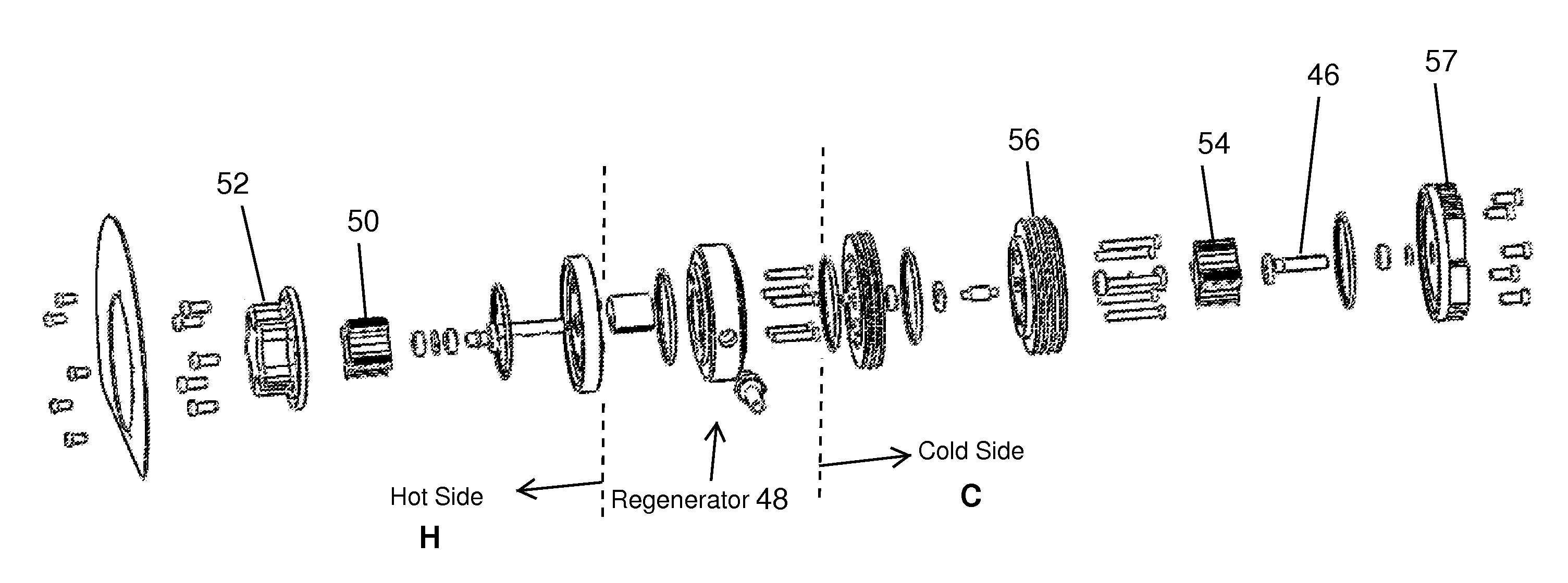
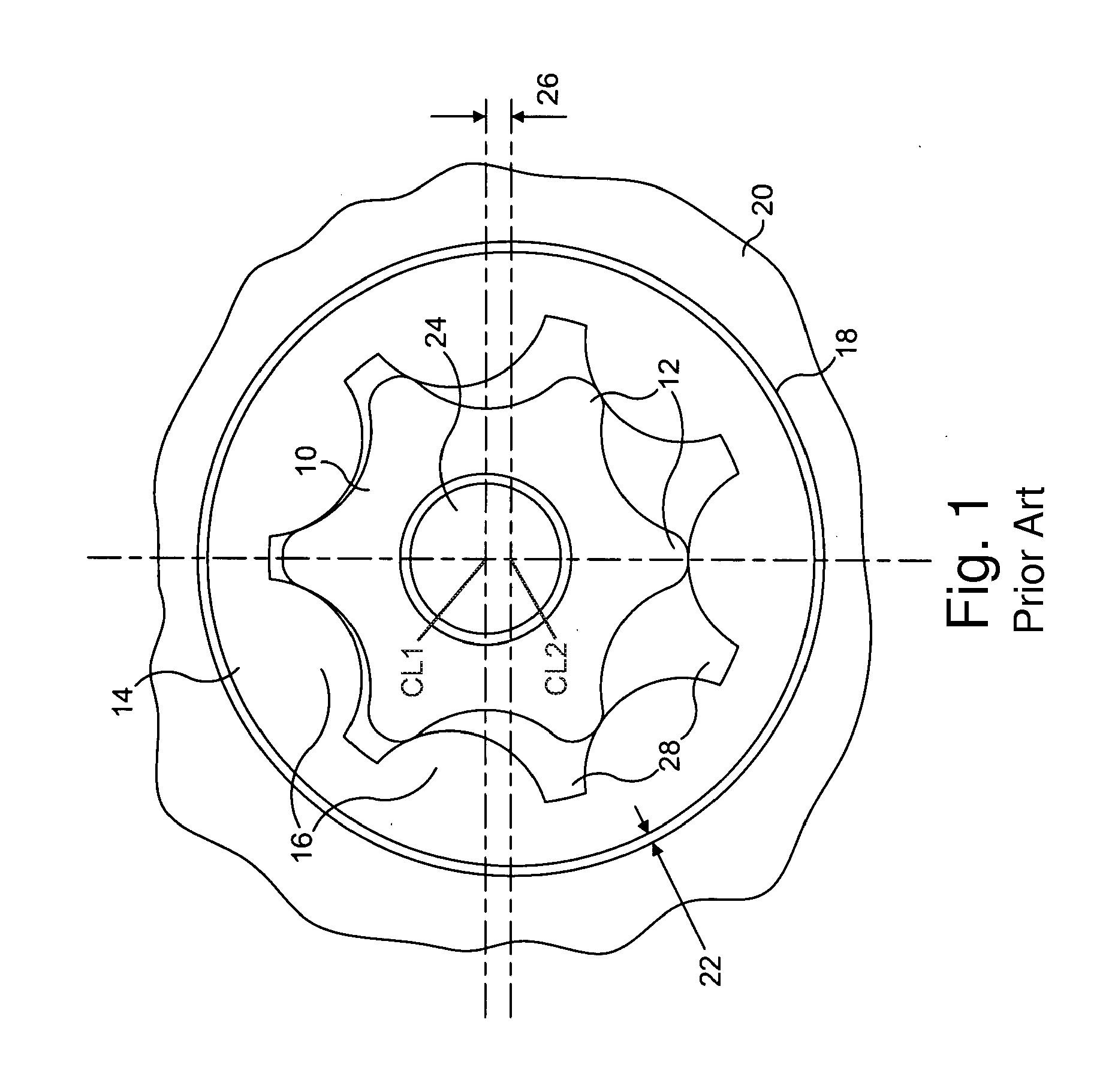
[0043]The present application illustrates an exemplary embodiment of a gerotor apparatus useful in a number of applications, in particular for power generation. Generally, the following detailed description describes gerotor apparatuses as being used in the context of a gerotor compressor; however, the following gerotor apparatuses may function equally as well as gerotor expanders or other suitable gerotor apparatuses. In addition, the present invention contemplates that the gerotor apparatuses described below may be utilized in any suitable application; however, the gerotor apparatuses described below are particularly suitable for a Stirling cycle engine.

[0044]With this device, any heat source, temperature differential, or cold source can be used to generate mechanical power on site or electricity with the help of an alternator. One clean and plentiful source for which this particular engine is designed is concentrated solar radiation producing goal temperatures of around 1000° F. ...


PUM


Abstract

Stirling cycle engines with hot and cold gerotor sets separated by an insulation barrier. The barrier has regenerative gas passages to allow gasses to flow therethrough thus connecting displacing chambers of the hot and cold gerotor sets. Each gerotor set has a rotor within a stator and displacing chambers created in an offset space therebetween. The stators may rotate about the rotors, or vice-versa. Either the rotor of the cold gerotor set has an axis of rotation offset with respect to the rotor of the hot gerotor set or the stator of the cold gerotor set has an axis of rotation offset with respect to the stator of the hot gerotor set, and the non-offset rotors or stators rotate about a common axis and are rotationally connected and create an angular phase offset between connected hot and cold chambers. The gerotor apparatuses may be utilized for a Stirling cycle engine for generating electricity, for example.

Description

FIELD OF THE INVENTION[0001]This invention relates generally to efficient power generation and other useful energy production such as heat engines and, more particularly, to a highly efficient gerotor-type rotary Stirling cycle engine and methods of operation.BACKGROUND OF THE INVENTION[0002]In a world of vanishing resources such as coal, oil, and natural gas, it is not only important to be more efficient in our use of energy, but also to improve on our abilities to efficiently extract energy from renewable resources such as hydroelectric, wind, geothermal and solar. To eventually replace fossil fuels with renewable sources of energy it must be feasible to do so. Currently renewable power conversion systems must operate at higher efficiencies if they are to provide the huge amounts of energy consumed by humans on the planet.[0003]There are currently several types of heat engines, each with its own characteristics and cycles. These heat engines include the Otto cycle engine, the Dies...

Claims


Application Information

Patent Timeline
IPC IPC(8): F02B53/00
CPCF02B53/00F01C1/103F01C11/004F01C21/08F02G1/043F02G1/044F02G2253/01F02G2270/10Y02T10/12B60K8/00F02G1/053F02G5/00F02G2243/30
Inventor FRANKLIN, ETHAN W.
Owner FRLIN ETHAN W
Why Eureka
Try Eureka