Sweetening of natural gas

a technology of natural gas and sweetening towers, applied in the field of purification, can solve the problems of liquid channeling, entrainment, foaming, and large size of conventional absorption towers in both amine sweetening systems and teg dehydration systems

Active Publication Date: 2014-10-16
GAS TECH INST
View PDF3 Cites 14 Cited by
  • Summary
  • Abstract
  • Description
  • Claims
  • Application Information

AI Technical Summary

Benefits of technology

[0008]A general object of one aspect of the invention is to provide an improved process for sweetening natural gas to liquefied natural gas specifications

Problems solved by technology

Conventional absorption towers in both amine sweetening systems and TEG dehydration systems are typically large in size, such as to require a large processing footprint, and heavy in weight.
Further, they generally pose operational challenges such as liquid channeling, flooding, entrainment, and foaming.
These and other challenges are often accentuated in a floating LNG application such as may arise in offshore processing such on a ship, barge or platform, and such as may introduce motion parameters to the processing scheme.
For example, such applications may suffer from motion-induced inefficiencies and process instability due to maldistribution of solvent in the column.

Method used


Image

  • Sweetening of natural gas
  • Sweetening of natural gas
  • Sweetening of natural gas

Examples


examples

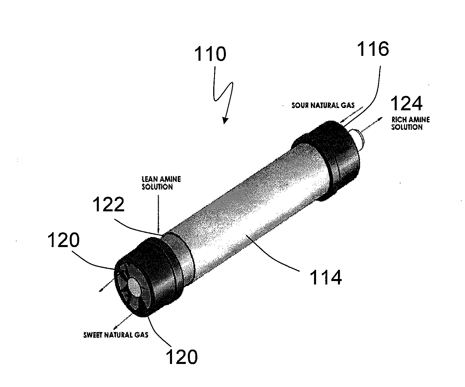
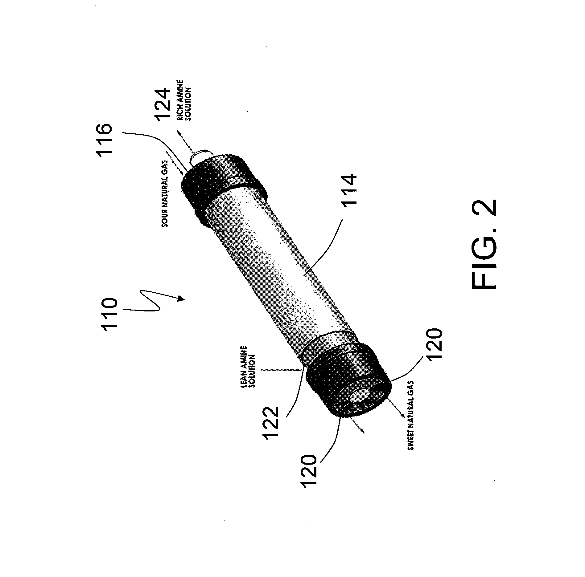
[0049]In these Examples, more than 30 two-inch diameter, 12-inch long cartridge-containing hollow fiber contactor modules with circa 10 ft2 of hollow fiber surface area and having varying physical characteristics of fiber pore size and porosity, fiber dimensions, fiber packing density and fiber surface areas were tested.

examples 1-6

[0050]In these Examples, module performance was tested for CO2 removal utilizing a DEA solvent system. The feed pressure was 500 psig and the feed contained about 8% by volume CO2 with the remainder nitrogen. The CO2 was efficiently removed to generate a product containing less than 2.0 vol. % residual CO2. The gas side pressure drop, the liquid side pressure drop, and the lean and rich loading of the DEA solvent were also measured. The best performing hollow fiber contactor results are summarized in the section below. This module was fabricated with hollow fiber PEEK hollow fibers that had an intrinsic CO2 permeance of 1000 GPU measured using pure CO2 at 30° C.

[0051]Test results and mass transfer coefficient calculations for this module are shown in Table 2. The gas-side flow pressure drop, the liquid-side flow pressure, and the lean and rich loading of the DEA solvent for this module are shown in Table 3.

TABLE 2InletKGa,CO2,Outlet%mol / (m3 · hr ·KG,KGa,Example%CO2, %RemovalKpa)cm / s...

examples 7-14

[0058]In these Examples, module performance was tested for CO2 removal utilizing a DEA solvent system. The gas inlet pressure was 950 psig, the gas inlet temperature was 77° F. and the feed contained about 1% by volume CO2 with the remainder nitrogen. The liquid inlet pressure was 950 psig and the liquid inlet temperature for Examples 7 and 8 was 105° F. and for Examples 9-14 was 78° F.

[0059]The hollow fiber contactor results are summarized in Table 4, below.

TABLE 4Inlet CO2,OutletTotal InletKGa,% CO2Examplevol %CO2, ppmvGas, SCFH(1 / s)Removal70.963150 ± 1052.60.01698.581.104140 ± 1026.40.00898.790.96380 ± 952.50.01699.0100.98465 ± 6104.90.03299.3110.98351 ± 5209.90.06599.4120.960 72 ± 10287.90.08999.2131.27066 ± 7319.00.09999.5141.150564 ±20 624.60.17694.3

[0060]The CO2 was efficiently removed to generate a product containing residual CO2 levels indicating the ability to satisfy LNG specifications, e.g., residual CO2 levels below 100 ppmv, preferably significantly below 100 ppmv, and...


PUM

PropertyMeasurementUnit
diameteraaaaaaaaaa
diameteraaaaaaaaaa
temperatureaaaaaaaaaa

Abstract

An exemplary embodiment can be a process for sweetening natural gas to liquefied natural gas specifications. The process can include providing a membrane contactor having a lumen side and a shell side. A feed natural gas is introduced to the lumen side of the membrane contactor. An absorption solvent is introduced to the shell side of the membrane contactor. CO2 and H2S are removed with the absorption solvent from the feed natural gas resulting in a sweetened natural gas containing less than 50 ppmv CO2 and less than 4 ppmv H2S. Corresponding or associated systems for such sweetening of natural gas are also provided.

Description

BACKGROUND OF THE INVENTION[0001]This invention relates generally to the purification, e.g., sweetening, of natural gas.[0002]Stringent specifications are typically applied to LNG (Liquified Natural Gas) processing. For example, carbon dioxide and often hydrogen sulfide are typically present in field gases and have to be removed to specific levels, e.g., less than 50 ppmv CO2 and less than 4 ppmv H2S) such as due to concerns related to processability, toxicity and corrosion, for example. More particularly, LNG processing typically requires cooling of natural gas to −160° C. This in turn requires that the CO2 concentration in the natural gas be less than 50 ppmv to avoid icing within the system.[0003]Current state of the art processing to achieve such CO2 concentration levels in natural gas is by physical or chemical absorption in a column based process. Alkanolamine absorption process is a current state of art technology for this purpose. These amines are used as aqueous solvents to...

Claims


Application Information

Patent Timeline
Patent Type & Authority Applications(United States)
IPC IPC(8): C07C7/00B01D53/22B01D53/14B01D69/08
CPCB01D53/145C10L3/102C07C7/005B01D53/1462B01D53/229B01D2053/224B01D2252/204B01D2252/20478B01D2256/245B01D2257/304B01D2257/504B01D69/08C10L3/103C10L3/104C10L2290/548C10L2290/567B01D53/1443B01D2252/20405Y02C20/40B01D53/14C10L3/10
Inventor ZHOU, SHAOJUNMEYER, HOWARD S.
Owner GAS TECH INST
Why Eureka
Try Eureka