Cooling Apparatus

a technology of cooling apparatus and cooling chamber, which is applied in the direction of electric devices, battery/fuel cell control arrangements, electric devices, etc., can solve the problems of thermal destruction of the power converter used in the above-described electric vehicle, such as the electric car or the hybrid car, and achieve the effect of efficient cooling and good responsiveness

Inactive Publication Date: 2014-10-23
HITACHI AUTOMOTIVE SYST LTD
View PDF9 Cites 41 Cited by
  • Summary
  • Abstract
  • Description
  • Claims
  • Application Information

AI Technical Summary

Benefits of technology

[0017]According to the cooling apparatus of the present invention, by configuring the first cooling system for cooling the cooled body from the first flow passage which cools the cooling medium using the radiator and the second flow passage which cools the cooling medium using the second cooling system, the flow

Problems solved by technology

Incidentally, it is known that there is a possibility that the power converter used in the above-described electric vehicle, such as the elec

Method used


Image

  • Cooling Apparatus
  • Cooling Apparatus
  • Cooling Apparatus

Examples


embodiment 1

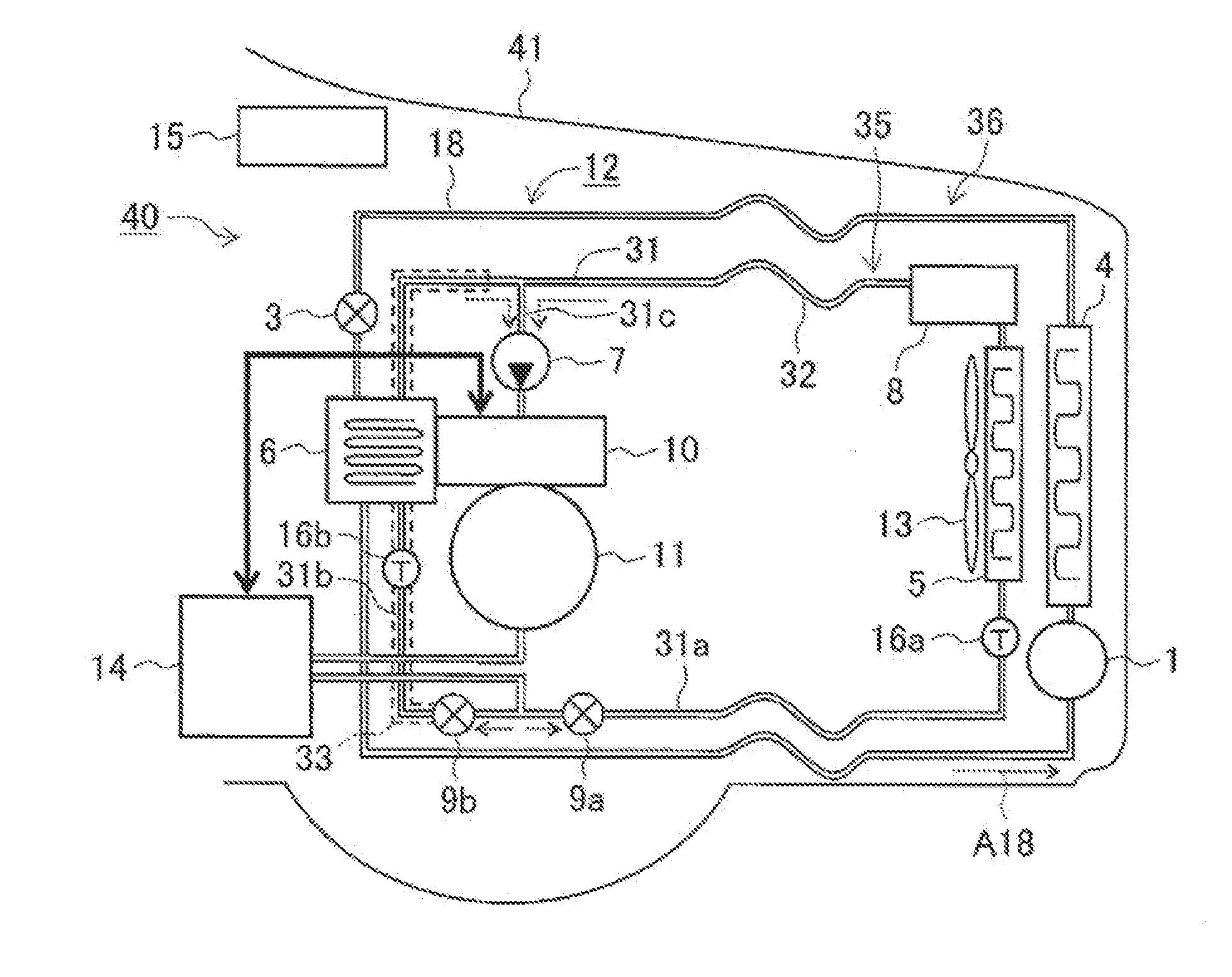
[0024]FIG. 1 illustrates a basic structure of a front side interior of a vehicle, to which Embodiment 1 of a cooling apparatus according to the present invention is applied. Here, in the illustrated example, a cooing apparatus 12 of Embodiment 1 is applied to an electric vehicle of a front wheel drive system. A right side in the drawing is a traveling direction of a vehicle 41, and an electric drive system 40 including a power converter 10, a motor 11, or the like is mounted in a vicinity of a front wheel of the vehicle 41. It should be noted that the cooling apparatus 12 of Embodiment 1 is also applicable to an electric vehicle with a rear wheel drive system or a four-wheel drive system, a hybrid electric vehicle equipped with an engine, or the like.

[0025]The illustrated electric drive system 40 of the electric vehicle 41 includes a storage battery 14 which stores driving energy, the power converter 10 which controls driving power supplying to the motor 11 using power supplied from...

embodiment 2

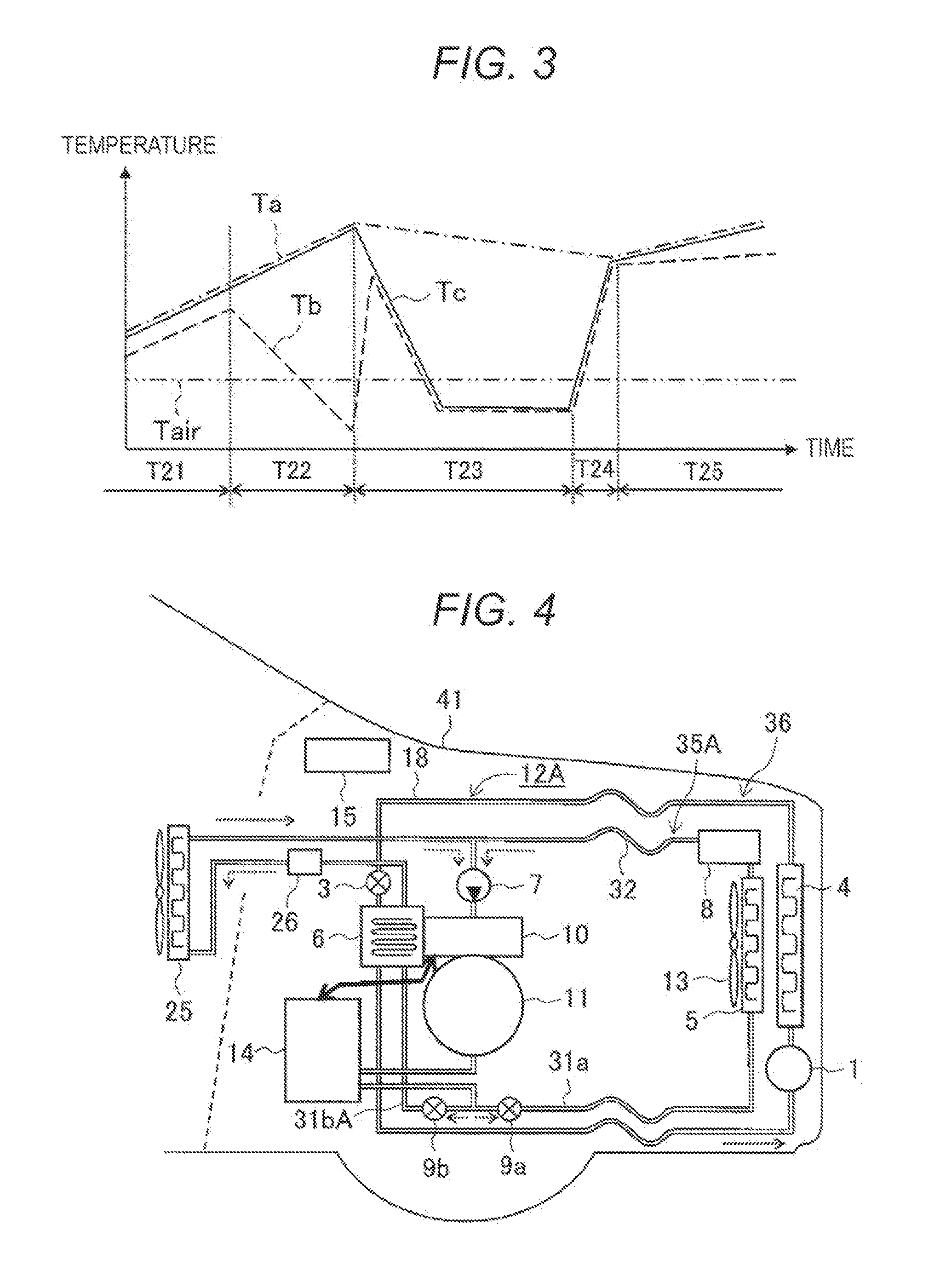
[0069]FIG. 4 illustrates a basic structure of a front side interior of a vehicle, to which Embodiment 2 of a cooling apparatus according to the present invention is applied. In Embodiment 2, the above-described second flow passage 31b of the water cooling system 35 of Embodiment 1 also serves as a flow passage for heating a vehicle cabin, and the other structures are the same as those in Embodiment 1. Consequently, the structures which are the same as those in Embodiment 1 are denoted using the same reference numerals, and detailed descriptions thereof are omitted.

[0070]In an illustrated cooling apparatus 12A of Embodiment 2, with respect to the above-described cooling apparatus 12 of Embodiment 1, a heater core (heat exchanger) 25 and a heater element 26 for heating a vehicle cabin are attached to a second flow passage 31bA of a water cooling system 35A. The above-described heater core 25 is a device which heats air introduced into the vehicle cabin by warm water. Further, the abov...


PUM


Abstract

A cooling apparatus for a vehicle includes a water cooling system that cools a cooled body by circulating cooling water; and a refrigeration cycle system that cools the cooling water to an outside air temperature or lower utilizing a gas liquid phase change of a refrigerant. The water cooling system includes a first flow passage that causes the cooling water cooled through a radiator radiating heat of the cooling water to outside air to flow through the cooled body; a second flow passage that causes the cooling water cooled to the outside air temperature or lower through an evaporator of the refrigeration cycle system 36 to flow through the cooled body provided at the first flow passage; and flow rate control units that control flow rates of the cooling water flowing in the first flow passage and the second flow passage.

Description

TECHNICAL FIELD[0001]The present invention relates to a cooling apparatus and, for example, relates to a cooling apparatus of an electric vehicle which jointly uses a water cooling system and a refrigeration cycle system.BACKGROUND ART[0002]In an electric vehicle, such as an electric car or a hybrid car, a power converter (inverter) converts DC power supplied from a high voltage storage battery (e.g., a lithium ion battery) into AC power, and a motor (e.g., a three-phase AC motor) is rotated using this AC power, thereby generating driving force of the vehicle. Further, when a speed of the vehicle is reduced, regenerative energy obtained by regenerative power generation of the motor is stored in the storage battery, thereby reducing waste of energy and realizing efficient energy utilization.[0003]Incidentally, it is known that there is a possibility that the power converter used in the above-described electric vehicle, such as the electric car or the hybrid car, is thermally destroye...

Claims


Application Information

Patent Timeline
IPC IPC(8): B60H1/00
CPCB60H1/00007H02K9/19B60H1/00392B60H1/08H02M7/003H02K2213/09B60L1/003B60L1/04B60L3/003B60L3/0061B60L15/20B60L2240/12B60L2240/34B60L2240/36B60L2240/421B60L2240/423B60L2240/425B60L2240/525B60L2240/545B60L2240/662B60L2270/145Y02T90/16Y02T10/72B60L50/51B60L58/26Y02T10/64Y02T10/70
Inventor YOKOYAMA, ATSUSHIOSAKA, TADASHIAKIYAMA, YUKIMIYAZAKI, HIDEKI
Owner HITACHI AUTOMOTIVE SYST LTD
Why Eureka
Try Eureka