Wind Turbine Gearbox Lubrication System

a technology of lubrication system and gearbox, which is applied in the direction of wind energy generation, liquid fuel engine components, non-positive displacement fluid engines, etc., can solve the problems of boundary lubrication conditions, less than adequate lubrication, contact fatigue, etc., to reduce or eliminate the effect of lubricant viscosity, lubricant viscosity reduction, and low viscosity

Active Publication Date: 2014-10-23
REM TECHNOLOGY INC
View PDF14 Cites 12 Cited by
  • Summary
  • Abstract
  • Description
  • Claims
  • Application Information

AI Technical Summary

Benefits of technology

[0024]In addition to increasing the operational efficiency of the wind turbine, the reduction in viscosity of the lubricant allows a finer inline filter to be employed. A heavy lubricant is difficult to pass through a fine filter and incurs significant pressure losses. In general inline filters are provided with a bypass that can open in response to excess pressure drop across the filter. Once the bypass opens e.g. during cold-start conditions or on clogging, the filter ceases to be effective in removing debris. Subsequent contamination can pass directly to the gear and bearing surfaces. According to the present invention, a finer filter may be used during normal operation with less risk of clogging. By removing a greater quantity of finer particles from the oil, potential damage to critical surfaces within the gearbox may be further reduced. Since damage due to debris leads on to further debris, the vicious circle may be broken and the lubricant and filters may have a significantly increased useful life. In this context, an inline filter is considered to be one that is active during commissioned use of the wind turbine gearbox and not one that is merely present for run-in purposes and thereafter bypassed or otherwise obsolete.
[0036]The additive package according to this invention comprises a reduced amount or none of any or all of the following: antiwear, anti-scuffing, anti-micropitting, extreme pressure, anti-foaming, anti-oxidation / oxidation inhibitor and friction modifying compounds. General examples of each class of additive compounds that may be reduced include: an antiwear, anti-corrosion, and extreme pressure compound comprising both sulfur and phosphorous and / or containing zinc or boron; an extreme pressure compound comprising sulfur; an antiwear compound comprising phosphorous, such as zinc dialkylditihiophosphate (ZDDP); a friction modifying compound comprising an alkylene amine compound, molybdenum, or both; a dispersant compound containing basic nitrogen; and antioxidants comprising an aryl amine. Moreover, antifoaming or defoamant agents comprising any or all of the following: dimethylsiloxane polymers, alkylmethacrylate polymers, alkylacrylate copolymers may be completely or essentially eliminated. As a consequence of the removal of such antifoaming additives, significantly finer particle filters may be used effectively without increasing operational losses.

Problems solved by technology

Operation of the system outside the preferred range of load, speed or temperature may lead to less than adequate lubrication.
Inadequate lubrication may lead to boundary lubrication conditions, contact fatigue and eventually rough cleavage of peak asperities (micropitting) from the metal surface.
Cleaved metal asperities, or particles and especially particles larger than 1 micron contaminate the lubricant and accelerate the wear process.
In particular, such particles may be extremely detrimental to the bearings which generally operate with a lower film thickness to that of the gears.
Consequently, gear life is shortened and premature catastrophic gear failure may occur.
These additives may however themselves be sensitive to certain conditions and can become ineffective or even detrimental.
They are also often environmentally undesirable.
However, it must be noted that Ra cannot distinguish between a surface that is planarized versus a surface that is ground or honed.
Various theories exist regarding the correct lubrication for use with superfinished components but in general, such surfaces operate outside the accepted ranges where tried and trusted traditional results apply.
Particles having a size greater than the operational lubricant film thickness may be considered potentially harmful.
Nevertheless, it is not always simple to remove them from the system since the finer the filter, the more difficult it is to circulate a lubricant through it.
As the viscosity increases, the system may become tolerant of larger debris but the filtering of such debris becomes more difficult due to the resistance of the filter to flow.
Additionally, parasitic frictional losses increase as a result of greater lubricant viscosity.
These in turn generate heat which causes the system to run hotter or require additional oil cooling capacity.
Exposure to elevated temperatures can result in lubricant deterioration due to e.g. thermal oxidation.
Air bubbles or inclusions are generally undesirable both due to the tendency to cause foaming but also because the presence of air inclusions can reduce the strength of the lubricant film.
The gears and bearings are highly loaded and operate under extremely harsh conditions that are unique to the wind power industry.
Changing the lubricant is also no easy chore since the gearboxes are located atop towers that can extend more than one hundred meters above the ground often located in harsh climates and remote regions on high terrain or offshore.
The approved viscosity is a significant compromise, since it may in fact be too low for the low speed input stage and is generally considered too high for high speed gear stages and especially the bearings.
High viscosity lubricants restrict proper bearing rolling and promote frictional heating and wear.
Nevertheless, for high viscosity lubricants, filters of such fineness are often ineffective and once initial run-in has been carried out may be replaced by 10 micron filters.
Additional, finer filters of 3 microns may be used in an offline configuration but these cannot guarantee full removal of all particulates.
By their nature the additives used are not always environmentally friendly and leaks to the environment would be damaging to the green image of the wind power industry.
In particular, sulfur and phosphorous are damaging to the environment.
Additionally sulfur and phosphorous containing additives may damage gearboxes by promoting micropitting and corrosion.
However this often leads to even more complex additives using additional compounds and processes.

Method used


Image

  • Wind Turbine Gearbox Lubrication System
  • Wind Turbine Gearbox Lubrication System
  • Wind Turbine Gearbox Lubrication System

Examples


Embodiment Construction

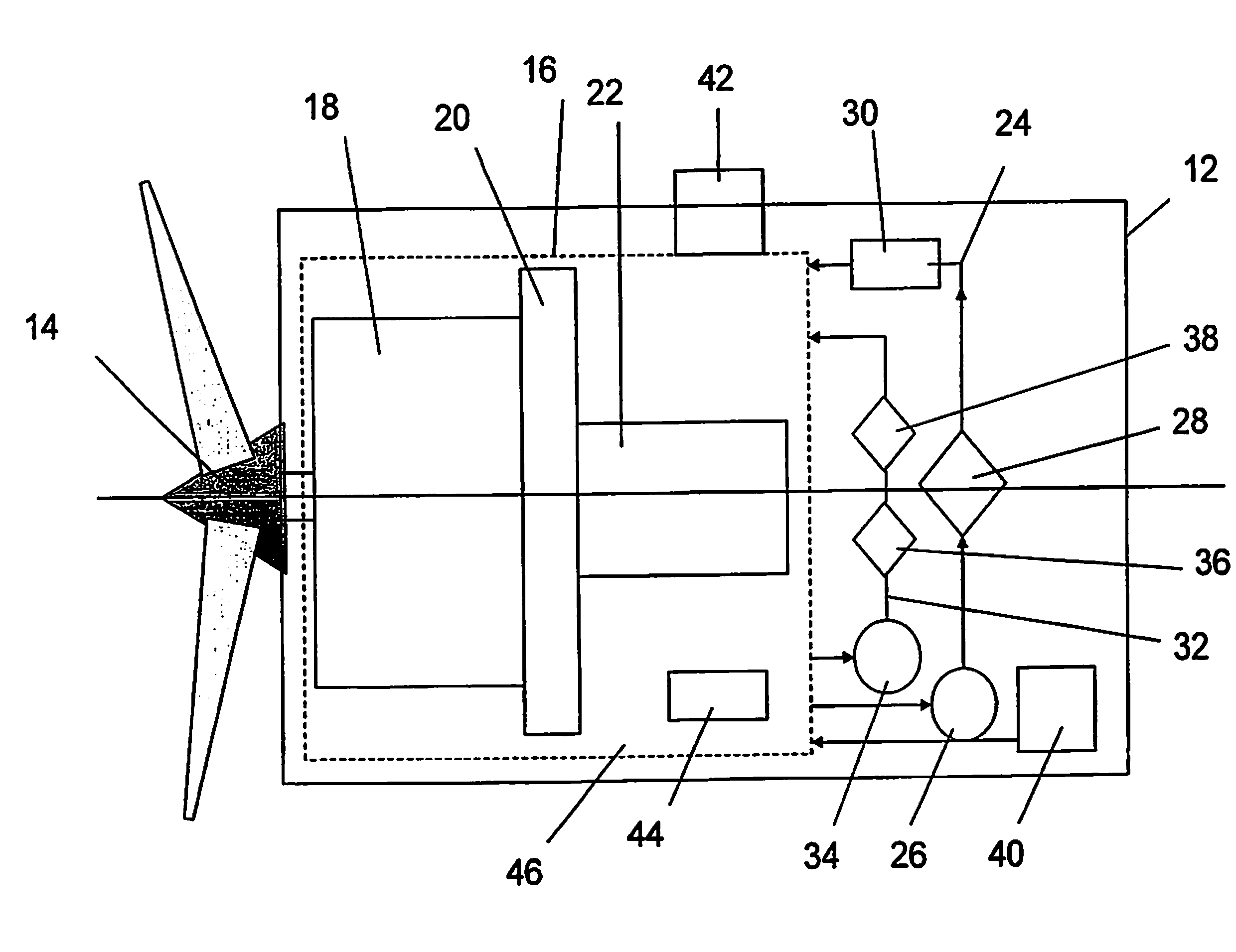
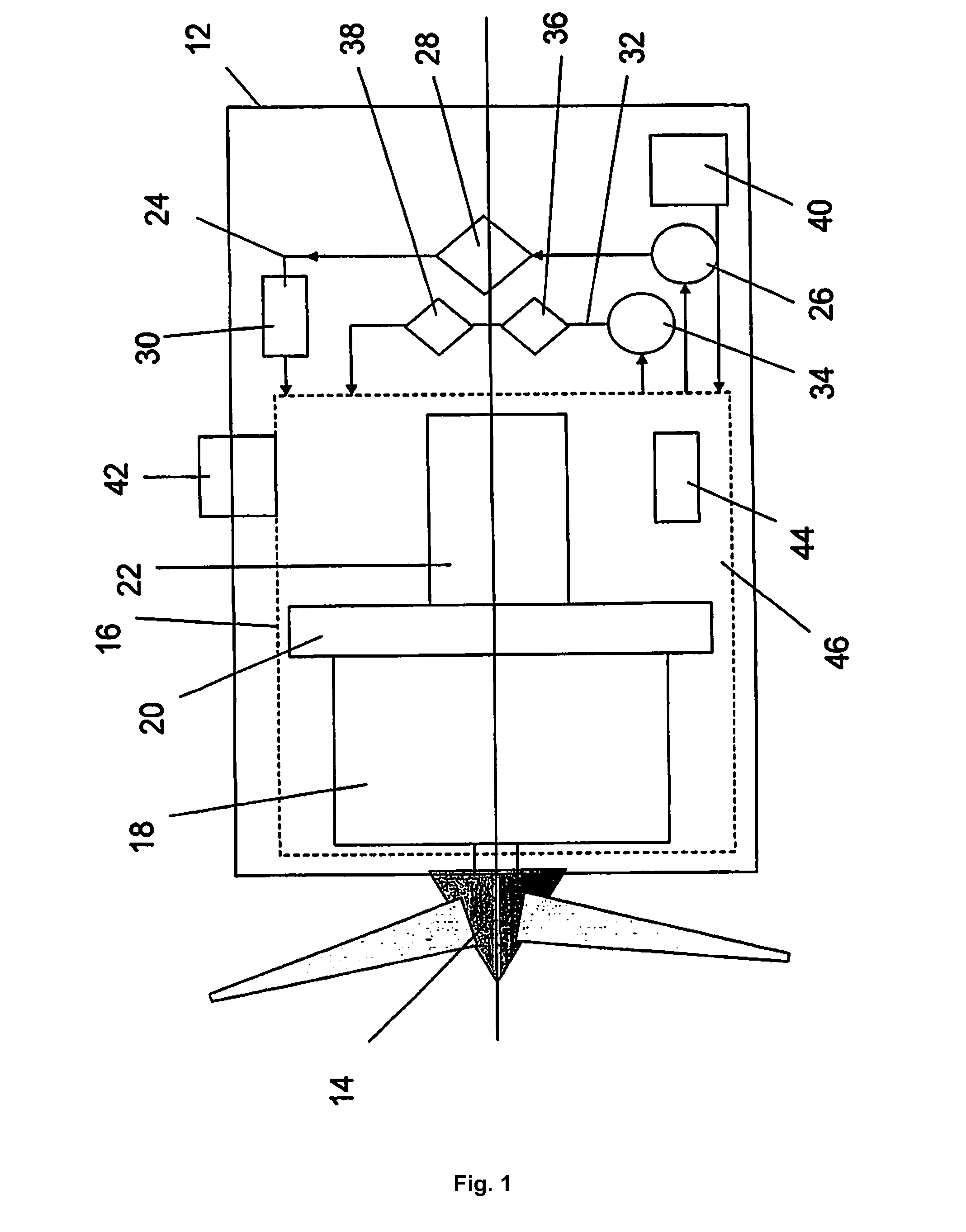
[0041]The following is a description of a prophetic embodiment of the invention, given by way of example only and with reference to FIG. 1 which shows a wind turbine 10 comprising a nacelle 12 and a rotor 14. The nacelle 12 houses a gearbox 16 including a low-speed input stage planetary gear 18, a bearing 20 and a high speed gear stage 22. Further intermediate stages may be present (not shown). As will be understood, the design of such a gearbox is relatively complex but is otherwise conventional and its design is largely unrelated to the present invention. Details of the gearbox design may be found in publications such as Recommendation to Comply with the Technical Criteria of the Danish Wind Turbine Certification Scheme Gearboxes, 2007 Danish Energy Authority or the Vestas Mechanical Operating and Maintenance Manual V90-3.0 MW, VCRS 60 Hz, 2007.

[0042]In addition to the gearbox 16, the nacelle 12 houses a lubrication circuit 24 comprising an inline pump 26, an inline filter 28 and ...


PUM


Abstract

A wind-turbine gearbox system includes an input gear stage having mating gear surfaces finished to a surface roughness of less than 0.25 micron and at least one bearing supporting the input gear stage. A lubrication circuit is arranged to deliver lubricant to the input gear stage and the bearing during operation of the wind-turbine and includes an inline filter for removal of particles of less than 2 micron from the lubricant prior to delivery. A lubricant for use in the system may have a relatively low viscosity compared to conventional wind turbine gearbox lubricants.

Description

BACKGROUND OF THE INVENTION[0001]1. Field of the Invention[0002]The invention relates generally to the lubrication of gearboxes and more particularly to systems for improving lubrication in relation to large wind turbine gearboxes having superfinished components.[0003]2. Description of the Related Art[0004]Engineering components in moving contact with one another generally require lubrication in order to prevent or reduce friction, heat and wear. The greater the load, speed or period of movement, the more critical is the lubrication. Gears, bearings and cams are all examples of engineering components that may be designed for thousands of hours of continuous operation. Only with correct lubrication can such operation be successfully achieved. Various principles of lubrication exist, including air bearings, hydrodynamic lubrication and particulate lubrication. The present invention is concerned with liquid lubrication in the form of oils, both natural and synthetic.[0005]Complex engin...

Claims


Application Information

Patent Timeline
Patent Type & Authority Applications(United States)
IPC IPC(8): F03D11/00F03D11/02
CPCF03D11/02F03D11/0008F16H57/0402F05B2260/98F05B2280/5011C10M171/02C10M2203/1006C10M2205/0285F03D80/70F16C2360/31F03D15/00C10N2030/40C10N2030/44C10N2030/43C10N2030/42C10N2040/04Y02E10/72
Inventor MICHAUD, MARK D.SROKA, GARY J.BENSON, RONALD E.WINKELMANN, LANE
Owner REM TECHNOLOGY INC
Why Eureka
Try Eureka