Engine arrangement with charge air cooler and egr system

Active Publication Date: 2014-10-30
VOLVO LASTVAGNAR AB
View PDF6 Cites 10 Cited by
  • Summary
  • Abstract
  • Description
  • Claims
  • Application Information

AI Technical Summary

Benefits of technology

[0020]According to an advantageous embodiment, the air bypass can enter the EGR system between a first EGR cooler and a second EGR cooler. The first EGR cooler can be a HT EGR cooler and the second EGR cooler can be a LT EGR cooler. The air bypass enters the EGR system downstream of the HT EGR cooler and upstream of the LT EGR cooler and the air is mixed with pre-cooled exhaust gas. As a consequence, the dimensions of the LT EGR cooler and the insulation thickness of the EGR line downstream of the HT EGR cooler can be reduced, since temperature of the mixed air/exhaust gas can be further decreased.
[0021]According to an advantageous embodiment, an EGR line segment can be arranged downstream of the air bypass port in the EGR line and can be adapted as a mixing chamber. The air bypass enters the EGR system either upstream of an EGR cooler or can be connected to a direct EGR line. The EGR line downstream of the air bypass port leads to th

Problems solved by technology

During this cooling process, EGR gas may become excessive, for example during engine start or during a cold start period, deteriorating the combustion efficiency in each cylinder and in the exhaust gas components.
Compressing air in the turbocharger increases the air temperature, which may cause a number of problems.
Excessive charge air temperatures can lead to detonation, which is highly detrimental to engines.
For a compression ignition engine having at least one turbocharger and an intake air cooler, operation of the engine at or around idle is difficult to optimize for various reasons.
First

Method used


Image

  • Engine arrangement with charge air cooler and egr system
  • Engine arrangement with charge air cooler and egr system
  • Engine arrangement with charge air cooler and egr system

Examples


Embodiment Construction

[0033]In the drawings, equal or similar elements are referred to by equal reference numerals. The drawings are merely schematic representations, not intended to portray specific parameters of the invention. Moreover, the drawings are intended to depict only typical embodiments of the invention and therefore should not be considered as limiting the scope of the invention.

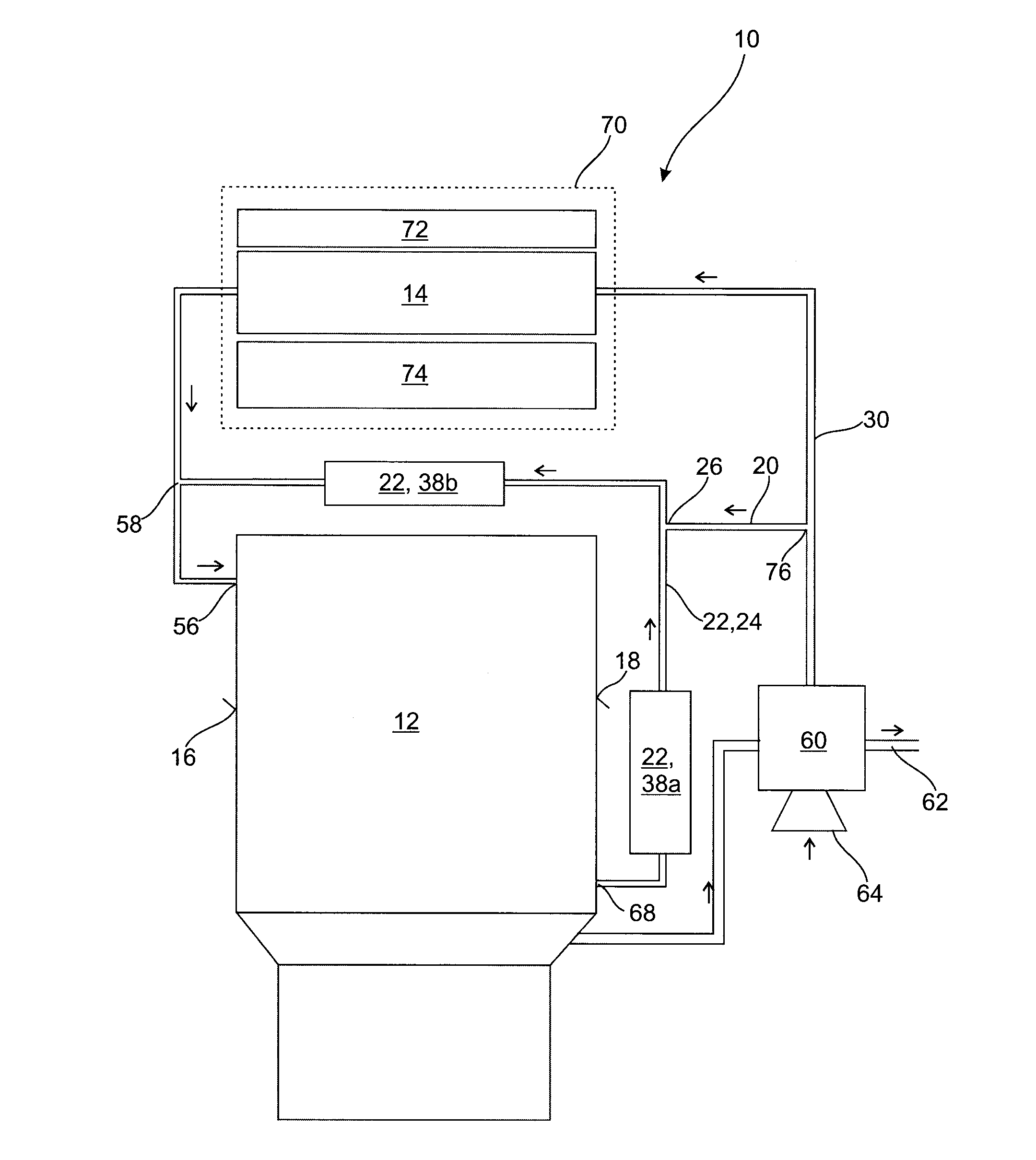
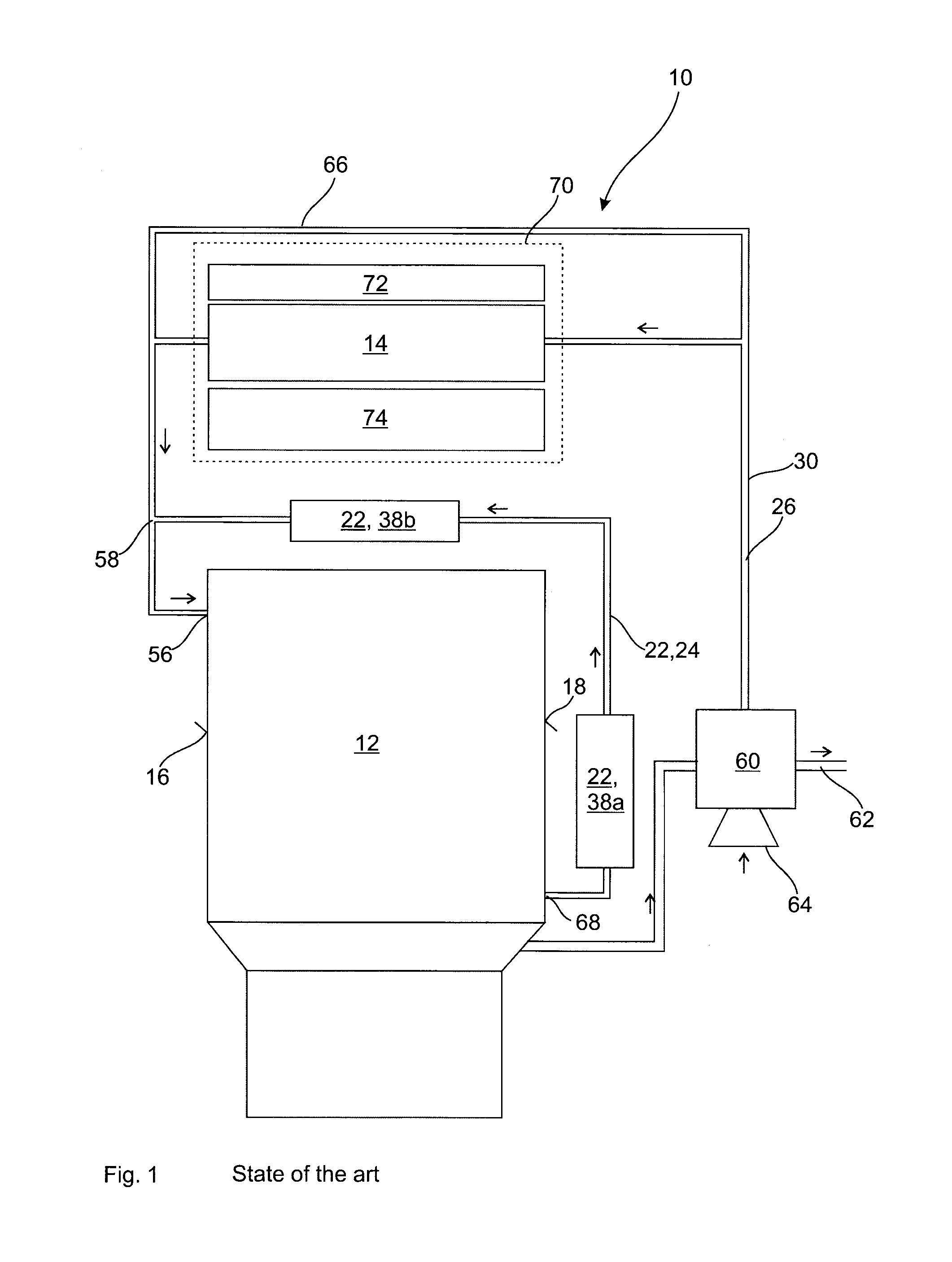
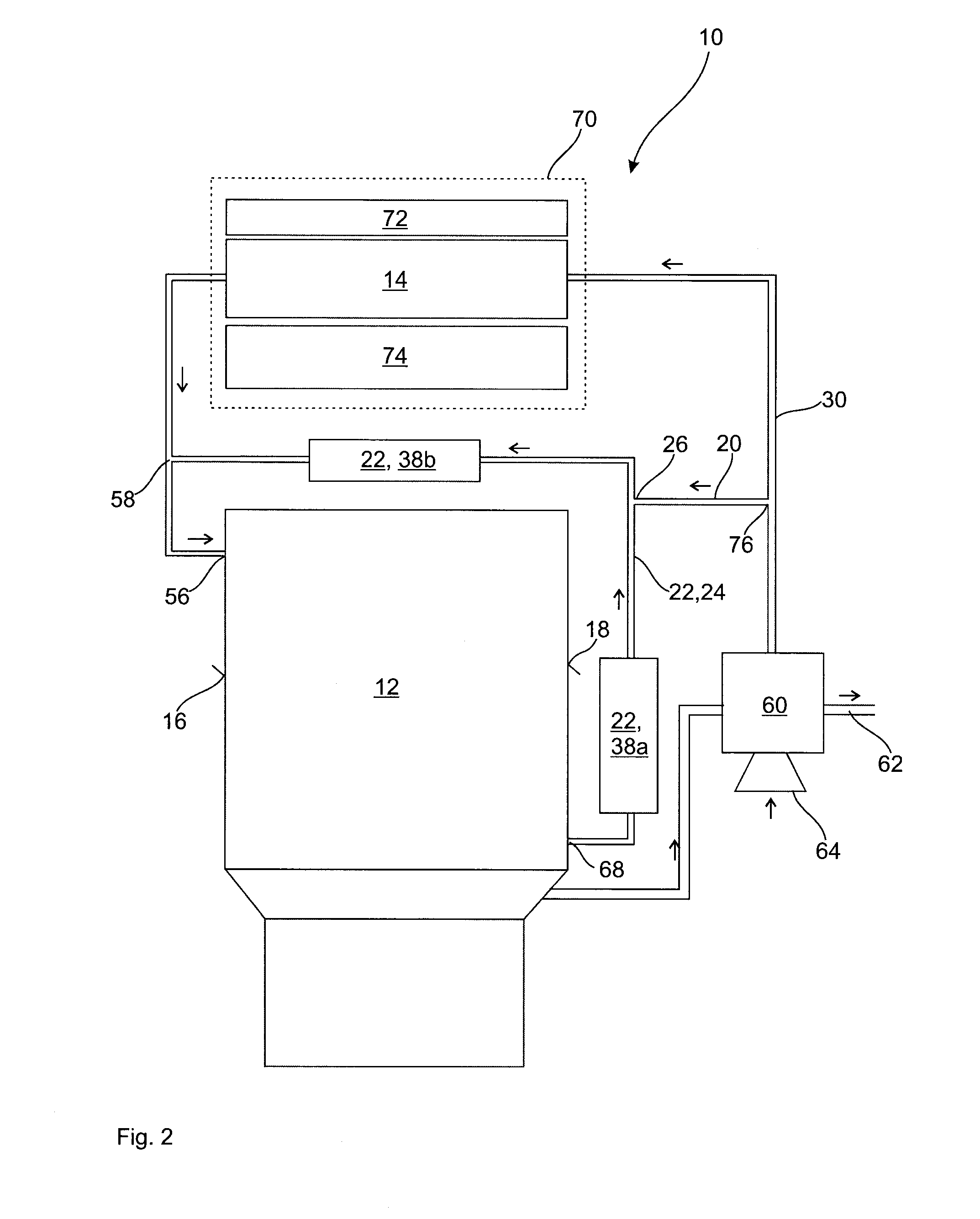
[0034]FIG. 1 schematically depicts a state-of-the-art engine arrangement comprising an engine 12, an EGR, system 22 and a charge air cooling system comprising a turbocharger 60 and a charge air cooler arrangement 70. The EGR system 22 recirculates exhaust gas produced by the engine 12 from a engine outlet side 18, which is a hot engine side to an engine inlet side 16 which is a cold engine side. Exhaust gas being released by the engine outlet side 18 usually has a temperature of between 100° C. (low load) and 700° C. (full load). Typically, the gas pressure of the exhaust gas may vary between 1.5 to 500 kPa. At least...


PUM


Abstract

An engine arrangement includes an engine, a charge air cooler connected to an engine inlet side of the engine, an air bypass for bypassing the charge air cooler, and including an EGR system connected between engine outlet side and an engine inlet side of the engine via one or more EGR lines. The air bypass enters the EGR system at an air-bypass port of an EGR line for mixing air with exhaust gas at the engine outlet side of the EGR system and/or upstream of an EGR cooler. An engine arrangement can also comprise an engine, a charge air cooler connected via an air line to an engine inlet side of the engine, an air bypass for bypassing the charge air cooler, and including an EGR system connected between an engine outlet side and an engine inlet side of the engine via one or more EGR lines. A control device is provided for controlling an engine inlet temperature of an air/exhaust gas mixture by controlling a ratio of cooled/uncooled air and/or cooled/uncooled exhaust gas in the air/exhaust gas mixture.

Description

BACKGROUND AND SUMMARY[0001]The present invention relates to an engine arrangement having an engine comprising an EGR system and a charge air cooler.[0002]It is known from the state of the art that an engine arrangement having an engine, preferably for a vehicle such as a truck, bus, lorry, car, boat or the like, comprises an EGR system. In internal combustion engines, exhaust gas recirculation (EGR) represents a nitrogen oxide (NOx) emission reduction technique used in petrol / gasoline and diesel engines. NOx primarily forms when mixture of nitrogen and oxygen is subjected to high temperatures. EGR works by recirculating an engine exhaust gas portion back to the engine cylinders. In a gasoline engine, this inert exhaust gas displaces the amount of combustible matter in the cylinder. In a diesel engine, the exhaust gas replaces some of the excess oxygen in the pre-combustion mixture. Since NOx formation progresses much faster at high temperatures, EGR reduces the amount of NOx genera...

Claims


Application Information

Patent Timeline
IPC IPC(8): F02M25/07
CPCF02M25/0715F02M26/13F02B29/0412F02B29/0418F02B29/0475F02M26/24F02M26/26F02M26/30F02M26/33F02M26/36F02M26/42F02B29/0425F02B29/0437F02M26/05Y02T10/12F02M26/22F02M26/25
Inventor KOVAC, ALEKSANDERDAHL, ERIKJEMT, KATARINA
Owner VOLVO LASTVAGNAR AB
Why Eureka
Try Eureka