A malpositioned hip prosthesis will not adequately restore the joint's
biomechanics, will not function properly, and is at
increased risk of intra-operative and post-operative complications.
A malpositioned prosthetic implant is particularly susceptible to
dislocation and early loosening because the prosthesis will not be well fitted or supported within the host's native bone.
The
biggest problem routinely faced by surgeons today concerning human hip replacement procedures is how to achieve proper acetabular prosthetic implant alignment.
However, precise measurement of these specific angles, and therefore proper placement of the prostheses, has been difficult to achieve, mostly because two of these angles are relative to the patient's
pelvis and the patient is covered by sterile surgical drapes during the course of the hip replacement operation.
It also has not been possible to monitor any change in position of the patient's
pelvis that can occur after draping the patient for the
surgery.
In many cases the
soft tissue is not tight enough to provide adequate stability and allow the most suitable prosthesis with adequate length to be implanted.
Currently there is no device to accurately measure the change in length of the leg caused by the operation.
This causes another common problem with the biggest
impact on patient's satisfaction, the discrepancy between length of the operative and non-operative legs.
All of these currently available techniques are cumbersome, intricate and / or complex.
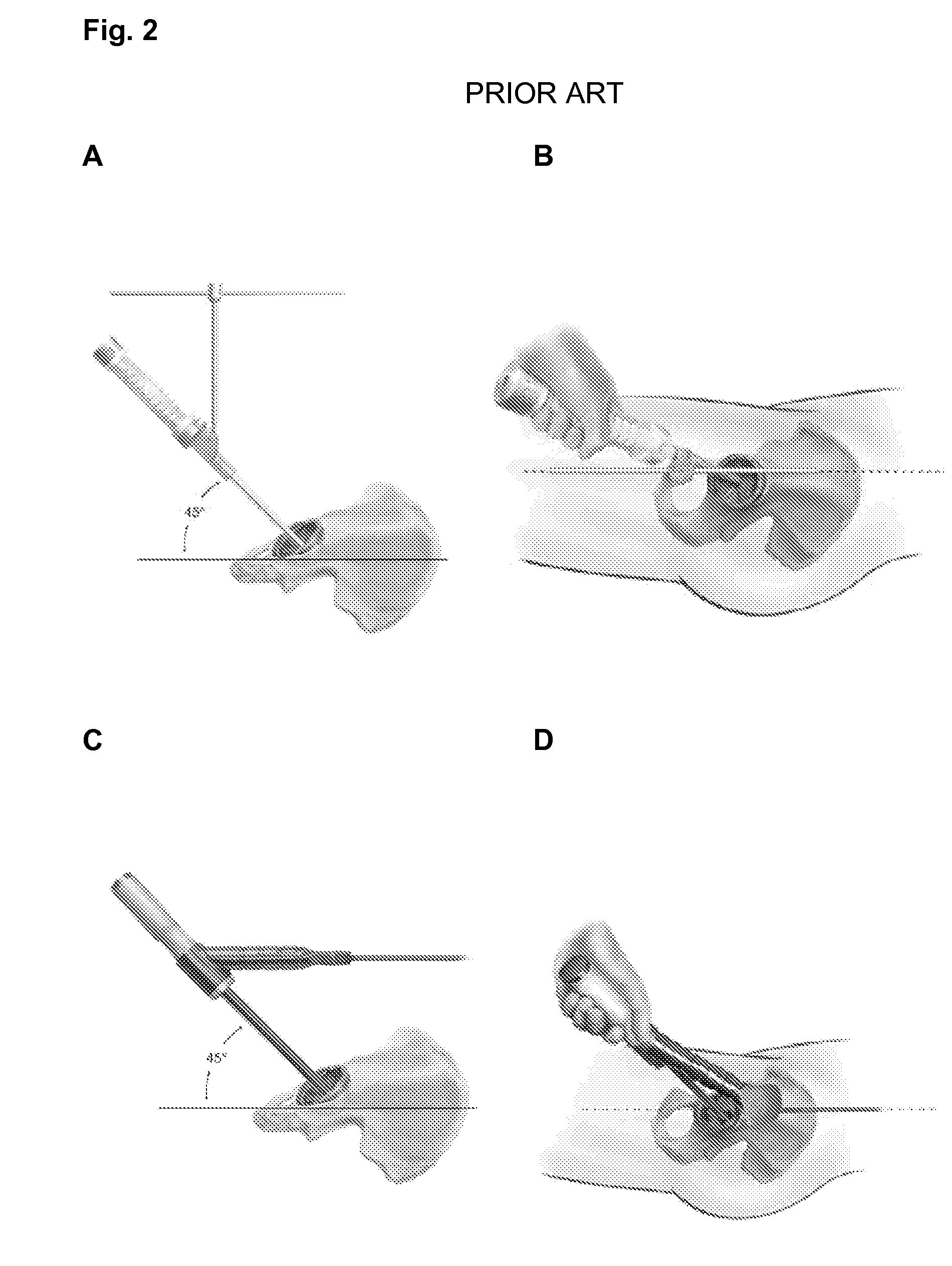
Nevertheless, the surgeon often discovers that the underlying assumptions for using the alignment guide device are false and ultimately finds that the
resultant angle of inclination for the prosthetic implant is often quite different from what was expected.
The other underlying problem with such conventional alignment guide devices is that the measurements are only subjective, i.e., they do not have any calibrated component by which to measure the angles of inclination or forward flexion in situ.
However, there are multiple disadvantages in following this procedure, among which are the following: This intra-operative x-
ray technique is frequently very time-consuming and can potentially increase the
risk of infection owing to the introduction of non-sterile x-
ray equipment into the
operating theater.
In addition, the obtained x-
ray images (which are directed antero-posteriorly through the host's
pelvis) are almost invariably of
poor quality; and useful bony landmarks (such as the
anterior superior iliac spine) are often obscured within the x-ray image.
These obstacles and disadvantages markedly hinder the surgeon's ability to detect or accurately measure the degree of pelvic tilt.
Moreover, even if a particular degree of pelvic tilt were discovered during the operation, there is no way for the surgeon to adjust the alignment of the prosthesis with the same
accuracy and precision as the measurement made using computerized digital tools.
Thus, even if intra-operative x-rays were used to determine the existence and degree of pelvic tilt, this measurement would only be of limited assistance in determining the proper inclination of the acetabular implant and would not help in any meaningful way in determining the proper degree of inclination / forward flexion for the
acetabular component.
Although the generally accepted range of intended anteversion is between 10° and 20°, the surgeon's
estimation of the anteversion of the
femoral stem has poor precision and is often not within the intended range of 10° to 20° of anteversion.
Alternatively, modular femoral components or stems with retroverted or anteverted necks could be used, but these components are much more expensive than non-modular femoral stems.
Nevertheless, the computerized
navigation system itself is very expensive equipment; and it requires both a pre-operative CT (computerized
tomography) scan and time-consuming pre-operative planning in order to be used effectively during the surgery.
In particular, intra-operative positioning of the digitizing frames is time-consuming and requires the placement of pins and numerous surgical incisions.
Also registration with digitizing probes is very time-consuming; and this technique is always vulnerable to an unexpected
software or hardware failure, which is not immediately replaceable in many instances.
Also, loosening of the implanted pins, especially in older and osteoporotic patients, is always a risk.
The main
risk factor is their location (inside the operating field) that leaves them at risk of getting accidentally jarred.
In addition, being in the surgical field is another reason that makes computerized navigation undesirable for many surgeons since it limits the surgical field.
Thus, more surgeons than ever before are still looking for an alternative and better method, especially after encountering the difficulties imposed by the computerized navigation guided system on multiple surgical occasions.


