Automated core drilling device capable of mating with a center-mounted core-catching device

a technology of automatic core drilling and center-mounted core catching device, which is applied in the direction of portable drilling machine, manufacturing tools, transportation and packaging, etc., can solve the problems of affecting the safety of workers, and requiring access to hazardous waste containers

Active Publication Date: 2014-11-13
SANDLER GREG
View PDF8 Cites 12 Cited by
  • Summary
  • Abstract
  • Description
  • Claims
  • Application Information

AI Technical Summary

Benefits of technology

[0007]Core drilling device is capable of drilling a large access hole in the top of a hazardous waste container, where the core drilling is performed by an automated computer-controlled process that adjusts the

Problems solved by technology

If the core sample were to fall into the hazardous waste container, this could cause the hazardous liquid inside to splash up or otherwise spread from the interior of the hazardous waste container to the outside, thereby causing harm to humans, property, and natu

Method used


Image

  • Automated core drilling device capable of mating with a center-mounted core-catching device
  • Automated core drilling device capable of mating with a center-mounted core-catching device
  • Automated core drilling device capable of mating with a center-mounted core-catching device

Examples


Embodiment Construction

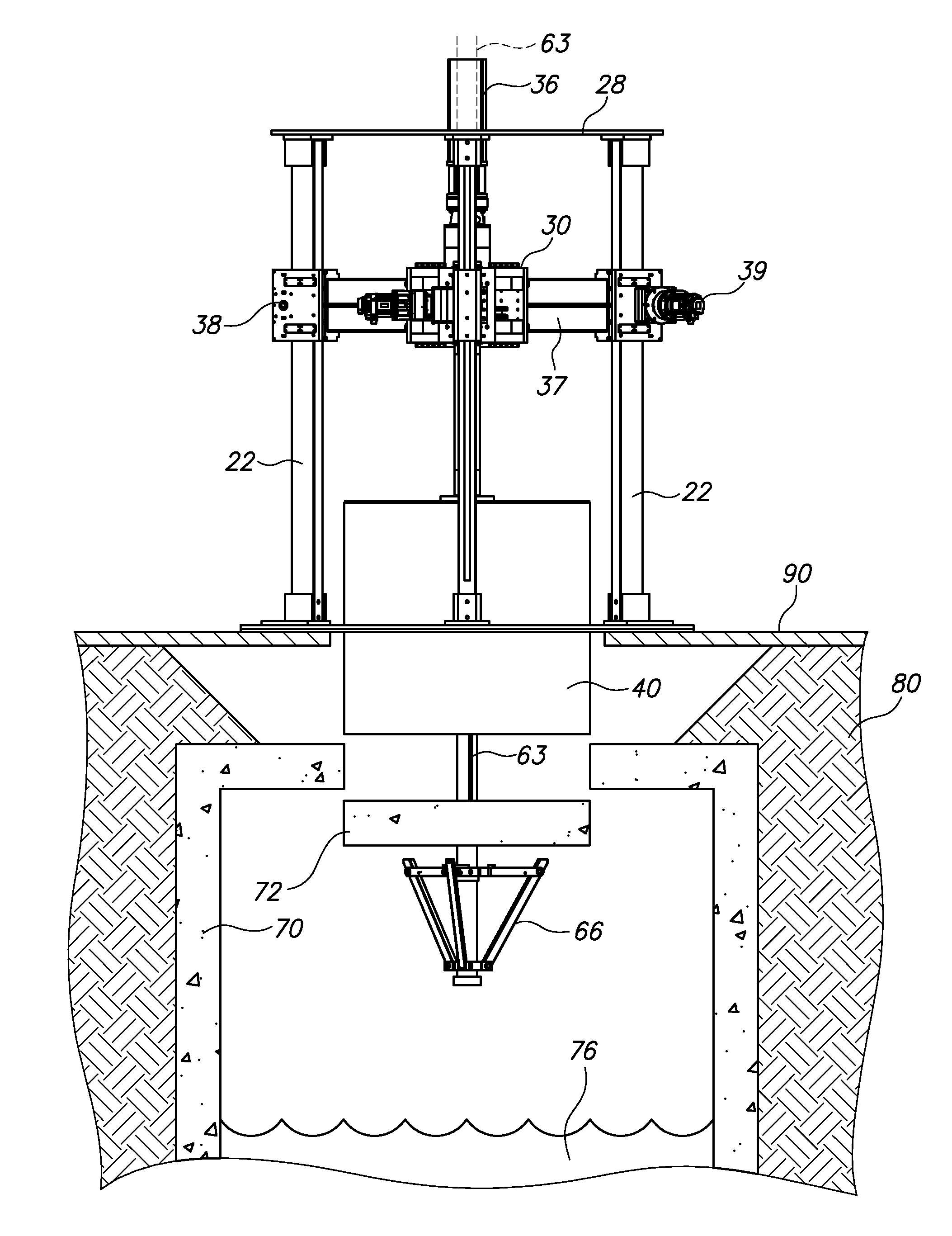
[0025]Automated core drilling device 10 comprises a rigid drilling tower 20 which functions to hold the drill bit and bit driveshaft exactly plumb or vertical as the drill bit is pushed downward and drilled into the hazardous waste container 70. If, during the drilling process, the rotating drill bit moves or “wanders” away from plumb or exact vertical alignment, even by a small fraction of an inch, the drill bit may snag or catch onto the sides of the hole being drilled into the hazardous waste container 70. Drill bit snags are undesirable because they can cause failure of the whole core drilling process or otherwise require the removal of the drill bit and restarting the drilling process.

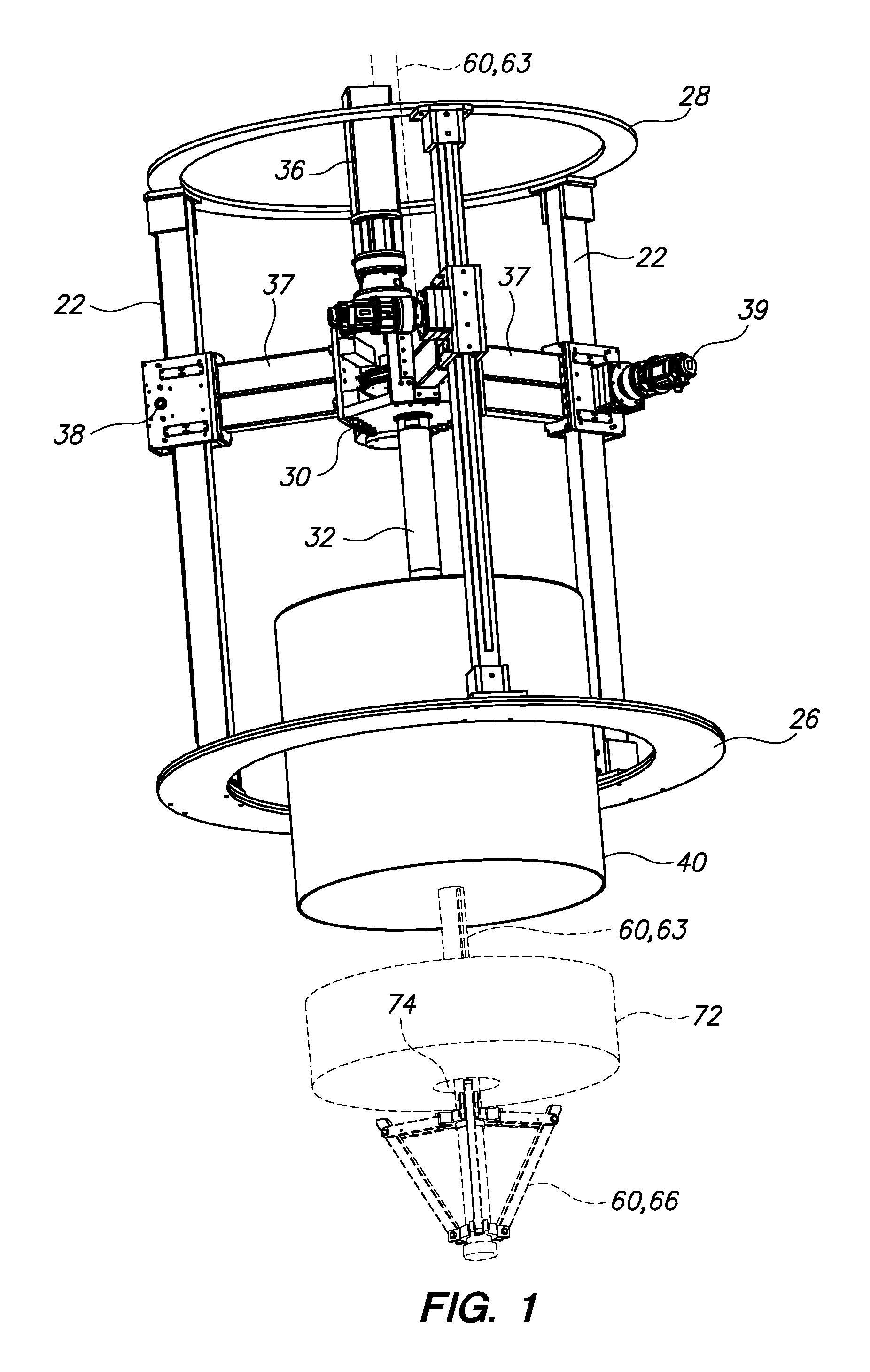
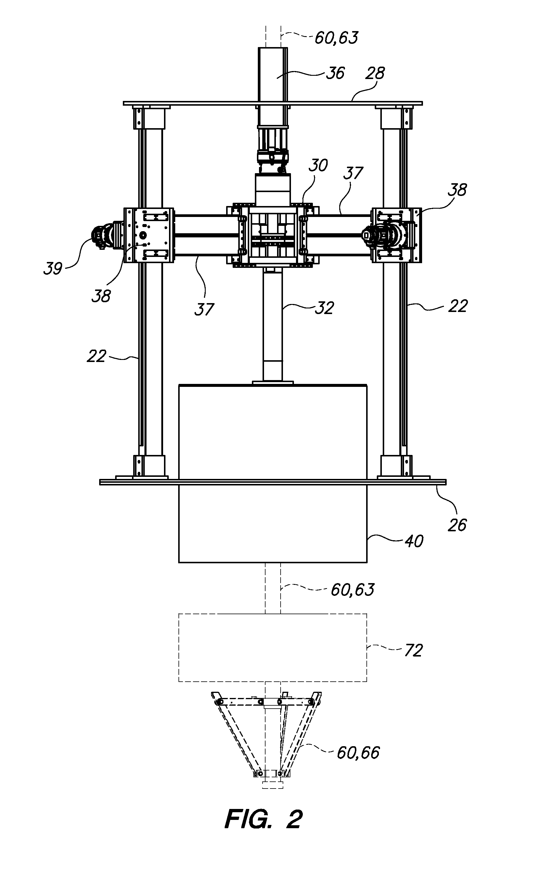
[0026]Rigid drilling tower 20 comprises: at least three vertical column members 22, a lower perimeter frame 26, and an upper perimeter frame 28. At least three vertical column members 22 are each rigid oblong members with a lower end and an upper end. At least three vertical column members are str...


PUM

PropertyMeasurementUnit
Lengthaaaaaaaaaa
Lengthaaaaaaaaaa
Lengthaaaaaaaaaa

Abstract

An automated core drilling device comprising a rigid drilling tower, a floating chuck assembly, and a drill bit. Rigid drilling tower comprising at least three vertical column members, a lower perimeter frame, and an upper perimeter frame. Floating chuck assembly comprising a drill bit axis-of-rotation vertical clearance channel, at least three horizontal support arms, at least three feed motor platforms, at least three feed motors, a hub casing, a hollow-centered bit driveshaft, a bit driveshaft sprocket, an offset spindle driveshaft sprocket, an offset spindle driveshaft, and an offset spindle motor. An automated core drilling device further comprising a computer with custom software, a monitor point for the electric current draw of said offset spindle motor or a monitor point for the revolution rate of said offset spindle driveshaft, and a control point for the electric current draw of each of said at least three feed motors.

Description

BACKGROUND OF THE INVENTION[0001]1. Field of the Invention[0002]The present invention relates, generally, to core drills that remove core specimens or cylindrical-shaped solid masses or plugs from a target solid, and, more specifically, to a core drill that is capable of mating with a core-catching device with a support member running through the center or longitudinal axis of the core specimen and connected to a core supporting means positioned underneath the core specimen, so that the core-catching device may catch and balance the core specimen, upon the successful drilling and detachment of the core specimen from the target solid.[0003]2. Description of Related Art[0004]Many endeavors require core specimens for the purpose of ascertaining physical and / or chemical properties of a target solid. Specimens are necessary because thorough laboratory testing must be conducted at laboratories located some distance from the target solid, so specimens must be detached from the target solid...

Claims


Application Information

Patent Timeline
IPC IPC(8): B23B39/24B23B45/02
CPCB23B39/24B23B45/02B23B2270/022B23B2270/48B23B2251/428B23B41/00Y10T408/55Y10T408/172E21B25/005B23B51/044
Inventor SANDLER, GREG
Owner SANDLER GREG
Why Eureka
Try Eureka