Physical system for chip-scale cpt atomic clock

a atomic clock and coherent technology, applied in the field of atomic clocks, can solve the problems of low stability of cpt atomic clocks, prone to accumulation of atoms, and low so as to improve the signal-to-noise ratio and contrast ratio, and enhance the cpt resonance signal

Active Publication Date: 2014-11-27
WUHAN INST OF PHYSICS & MATHEMATICS CHINESE ACADEMY OF SCI
View PDF5 Cites 8 Cited by
  • Summary
  • Abstract
  • Description
  • Claims
  • Application Information

AI Technical Summary

Benefits of technology

[0017]In view of the above-described problems, it is one objective of the invention to provide a physical system for a chip-scale CPT atomic clock that is adapted to centralize the atomic at the “0-0 energy level”, enhance CPT resonance signal, and improve the signal-to-noise ratio and the contrast ratio. Besides, all components of the system are suitable for integration, thereby realizing miniaturization of passive CPT atomic clock.

Problems solved by technology

However, such a scheme is disadvantageous in that the atom is prone to be accumulated at ground-state magnetic sublevels having a minimum (or maximum) magnetic quantum due to an optical pumping effect of the circularly polarized laser on magnetic hyperfine splitting atomic sublevels.
Thus, the signal contrast (a ratio between an amplitude of the photocurrent signal increased by CPT resonance and an amplitude of the photocurrent signal of non-resonance) is not high and the stability of the CPT atomic clock is not high.

Method used


Image

  • Physical system for chip-scale cpt atomic clock
  • Physical system for chip-scale cpt atomic clock
  • Physical system for chip-scale cpt atomic clock

Examples


Embodiment Construction

[0038]For further illustrating the invention, experiments detailing a physical system for a chip-scale CPT atomic clock are described below. It should be noted that the following examples are intended to describe and not to limit the invention.

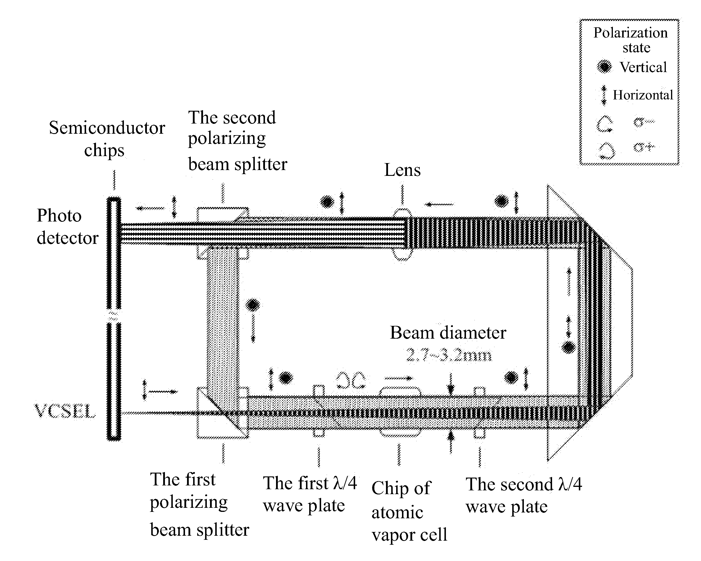
[0039]As shown in FIG. 7, a physical system for a chip-scale CPT atomic clock comprises: a VCSEL device, a first polarizing beam splitter 6a, a first λ / 4 wave plate 7a, a chip 8 of an atomic vapor cell, a second λ / 4 wave plate 7b, a reflection device, a lens 10, a second polarizing beam splitter 6b, and a photo detector 11. The first polarizing beam splitter 6a, the first λ / 4 wave plate 7a, the chip 8 of the atomic vapor cell, the second λ / 4 wave plate 7b, and the reflection device are disposed in sequence. The lens 10, the second polarizing beam splitter 6b, and the photo detector 11 are disposed in sequence. A linearly polarized circular divergent beam 12a is sent out by the VCSEL device and goes through the first polarizing beam splitter 6a...


PUM


Abstract

A physical system for a chip-scale coherent population trapping (CPT) atomic clock. The physical system includes: a vertical-cavity surface-emitting laser (VCSEL) device, a first polarizing beam splitter, a first λ/4 wave plate, a chip of an atomic vapor cell, a second λ/4 wave plate, a reflection device, a lens, a second polarizing beam splitter, and a photo detector. The first polarizing beam splitter, the first λ/4 wave plate, the chip of the atomic vapor cell, the second λ/4 wave plate, and the reflection device are disposed in sequence. The lens, the second polarizing beam splitter, and the photo detector are disposed in sequence.

Description

CROSS-REFERENCE TO RELATED APPLICATIONS[0001]This application is a continuation-in-part of International Patent Application No. PCT / CN2012 / 078270 with an international filing date of Jul. 30, 2012, designating the United States, now pending, and further claims priority benefits to Chinese Patent Application No. 201210033807.6 filed Feb. 15, 2012. The contents of all of the aforementioned applications, including any intervening amendments thereto, are incorporated herein by reference. Inquiries from the public to applicants or assignees concerning this document or the related applications should be directed to: Matthias Scholl P. C., Attn.: Dr. Matthias Scholl Esq., 245 First Street, 18th Floor, Cambridge, Mass. 02142.BACKGROUND OF THE INVENTION[0002]1. Field of the Invention[0003]The invention relates to the field of the atomic clocks, and more particularly to a physical system for a chip-scale coherent population trapping (CPT) atomic clock.[0004]2. Description of the Related Art[0...

Claims


Application Information

Patent Timeline
Patent Type & Authority Applications(United States)
IPC IPC(8): H03L7/26H01S1/06
CPCH01S1/06H03L7/26G02B27/283G04F5/145
Inventor GU, SIHONGZHANG, YIQU, SUPINGSHI, XUEMING
Owner WUHAN INST OF PHYSICS & MATHEMATICS CHINESE ACADEMY OF SCI
Why Eureka
Try Eureka