
Inhalation device with feedback system

a feedback system and inhalation device technology, applied in the field of inhalation, can solve the problems of increasing the likelihood that aerosol particles or droplets impact the throat of a patient rather than the lungs, affecting the specific delivery of aerosols through the inhalation route of administration, and affecting the effect of inhalation manoeuvre, so as to facilitate the immediate correction or adaptation of the inhalation manoeuvr

Active Publication Date: 2014-12-04
VECTURA LTD
View PDF7 Cites 60 Cited by
  • Summary
  • Abstract
  • Description
  • Claims
  • Application Information

AI Technical Summary

Benefits of technology

The invention is a device that helps users inhale air at a certain flow rate and pressure. It includes a device that restricts the air flow and a feedback system that tells the user if they are inhaling correctly. This device helps users improve their inhalation maneuver so that the aerosol is delivered to the respiratory system effectively.

Problems solved by technology

However, specific delivery of aerosols by means of the inhalation route of administration is not straight-forward.
While such high flow rates may be necessary in dry powder inhalers to disperse the powdered formulation, they are not desirable for other inhalation devices which emit a pre-dispersed aerosol and they increase the likelihood that aerosol particles or droplets impact in the throat of a patient rather than the lungs.
Throat deposition not only means that the respective fraction of the therapeutic compound is lost, but also an increased risk of systemic or local side effects.
In addition, when inhaling too fast through a device providing flow resistance, as is e.g. already common for dry powder inhalers, the underpressure increases.
However, such training is often perceived as inconvenient by the patient and / or the health professional.
In particular children, elderly patients, patients with motoric difficulties or mental limitations are often not able to perform a breathing manoeuvre correctly as instructed.
Thus the success of training alone is limited.
Furthermore, these issues become even more important when the number of breaths required to administer a desired dose increases.
While, for example, many dry powder inhalers, pressurised metered dose inhalers and / or soft mist inhalers deliver the required dose within just one or two inhalation manoeuvres upon actuation, drug administration with most nebulisers, such as ultrasonic nebulisers, jet nebulisers and / or vibrating mesh nebulisers typically involves a larger number of inhalation manoeuvres and thus longer administration times. The risk of deviating from a trained breathing manoeuvre increases with administration time; e.g., due to distraction or getting less concentrated.
Furthermore, an underpressure which may be well tolerable for one or two breaths only, e.g., inhaling at −40 mbar with a dry powder inhaler, can become rather inconvenient and exhausting when more inhalation manoeuvres are required.
One of the limitations of such systems which control flow and volume is that they are not readily portable.
It is difficult to implement the control features and functionalities within a small handheld device, which is the type of inhaler that is preferred by some patients due to its portability.
However, it is difficult and undesirable to rely solely on flow restriction in order to ensure a desirable low inspiratory flow rate.
Hence, it can be necessary to choose a lower flow resistance for more severely affected patients at the cost of not being able to prevent patients from using higher flow rates, e.g. up to about 25−30 L / min instead of a desired flow rate in the range of e.g., 15 L / min.
As mentioned above, such pronounced underpressure is undesirable because it induces a progressive constriction of small alveoli and bronchi, with the consequence that less drug can be deposited there.
Since the inhalation devices equipped with a variable flow restrictor according to EP 2 283 887 B1 do not provide any control of the underpressure, this approach does not ensure proper, reproducible inhalation manoeuvres.
In addition, EP 2 283 887 B1 also does not disclose any control of other inspiratory parameters such as the inhaled volume or inspiration time.
While the document also mentions the possibility of using audible feedback to a patient to encourage slow inhalation, it is highly unlikely that such general instruction will enable a patient to actually achieve inhalation at a particular target flow rate and / or underpressure.
If the breathing pattern is too weak or too unsteady, the drug-laden pulse will not be delivered or stop early.
However, US 2005 / 087189 A1 does not disclose any intention or means for controlling certain important parameters relating to the breathing manoeuvre, in particular a desirable inspiratory flow rate, inhaled volume, and / or underpressure.
However, it is difficult for patients to achieve a desirable low flow rate of e.g. 12 to 18 L / min on the basis of this type of feedback alone.
Rather, most patients would tend to produce a substantially fluctuating inspiratory flow rate, leading to variable drug deposition and unpredictable therapeutic effect.
The feedback system requires the patient to be fully concentrated on the feedback signals, which may be difficult in particular for children and elderly patients, but also for most other patients under treatment regimen which require long inhalation times.

Method used


Image

  • Inhalation device with feedback system
  • Inhalation device with feedback system
  • Inhalation device with feedback system

Examples


example 1

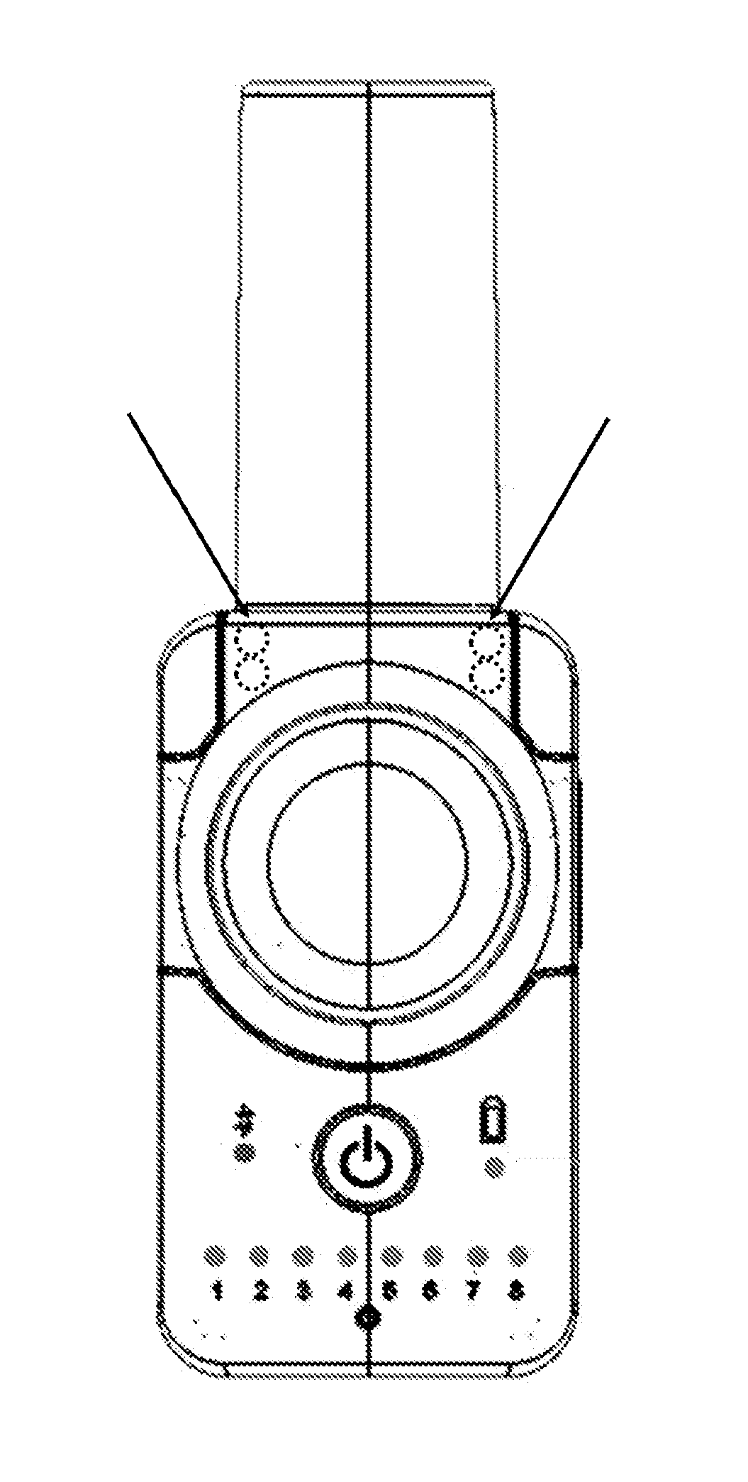
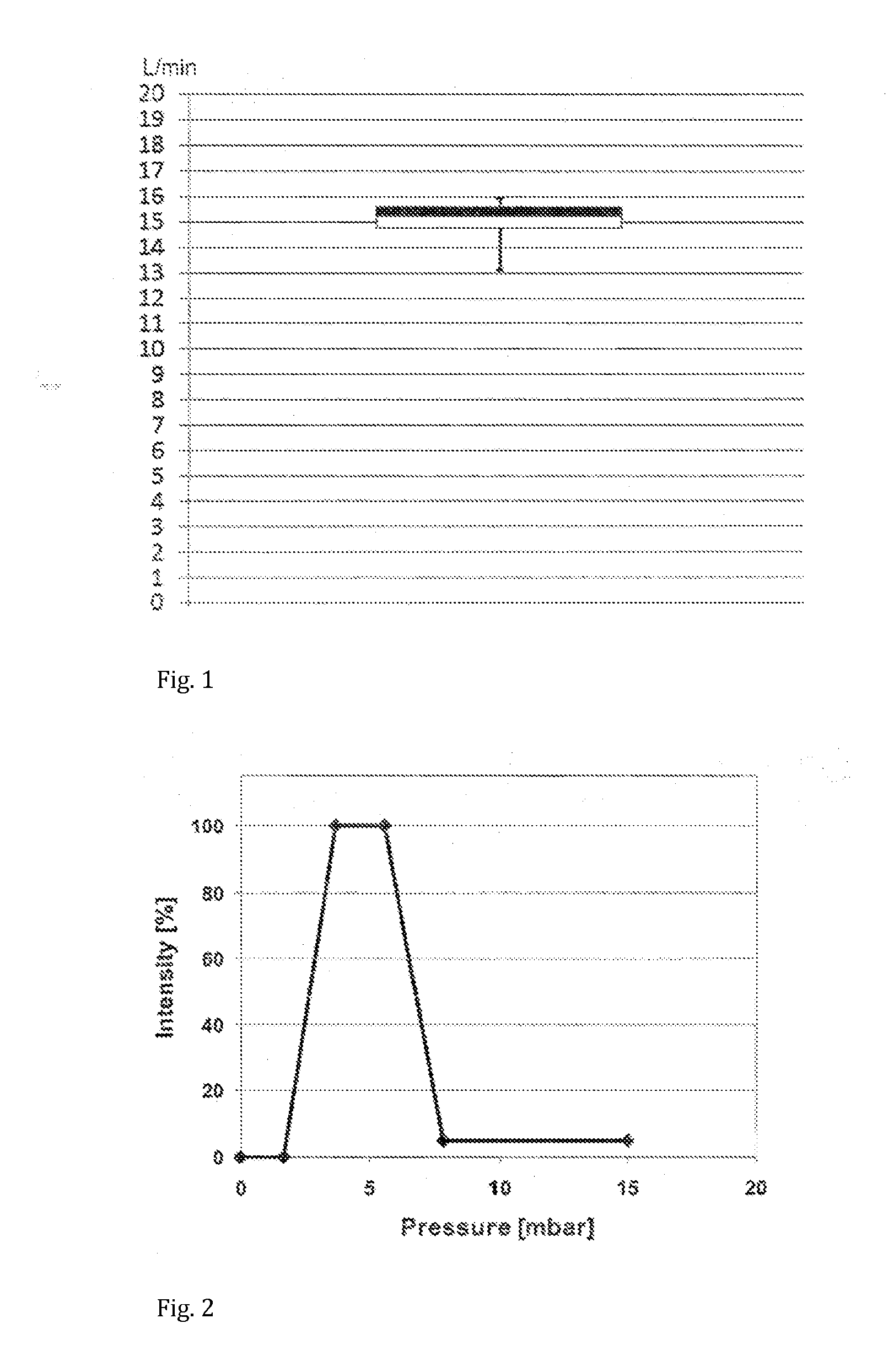
[0105]A hand-held nebuliser according to the present invention comprising a vibrating mesh-type aerosol generator, a flow restrictor and a user feedback system was configured and tested as follows. The flow restrictor was responsive to the inspiratory pressure. The inhalation parameter was the inspiratory flow rate, whose target range was set at 15±3 L / min. A pressure sensor was incorporated within the flow channel such as to measure the inspiratory pressure and indirectly determine the inspiratory flow rate. The signalling device comprised light-emitting diodes (LEDs) capable of emitting green light of variable intensity. Two sets of LEDs were incorporated inside the device such as to illuminate the mouthpiece, which itself was made from translucent polypropylene. The feedback system was configured to emit green light to illuminate the mouthpiece with the highest intensity when the inspiratory flow rate is within the target range. This flow rate was determined via a pressure value ...

example 2

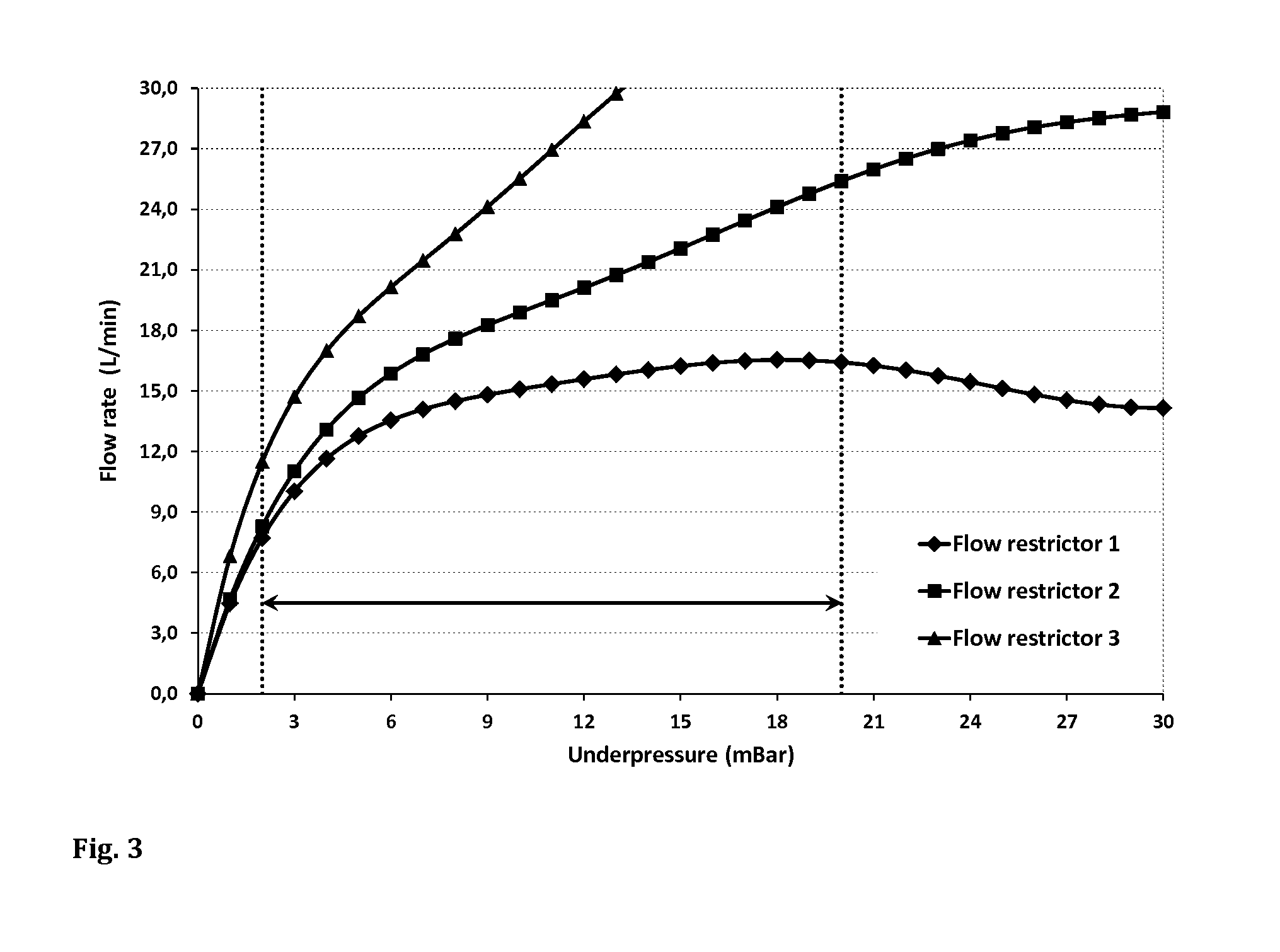
[0108]A hand-held nebuliser similar to Example 1 was used to test three different flow restrictors, all of which were responsive to inspiratory pressure. Again, 27 volunteers (21-72 years of age), of which 13 had no previous experience with nebulisers or other inhalers, were asked to perform 5 inhalation manoeuvres using the experimental device, with a short explanation given to the volunteers that they should aim for a green light at maximum intensity and adjust their inhalation accordingly if light intensity decreases.

[0109]FIG. 3 shows the underpressure-flow rate graphs of the three flow restrictors together with the target pressure range from about −2 mbar to about −20 mbar (indicated by the area between the two dotted lines). With all three devices, the flow resistance increases with increasing absolute value of the negative pressure, as indicated by the relatively smaller increase of the corresponding flow rate at high absolute pressure values. The higher the gradient of the c...


PUM


Abstract

The invention provides an inhalation device for enabling a user to inhale at a desired inspiratory flow rate and / or pressure, comprising a feedback system configured to indicate to a user by means of a signal during an inhalation manoeuvre whether an inhalation parameter, such as the inspiratory flow rate, is within a predefined target range. The signal may be an optical or a non-optical signal, such as a light signal, an acoustic signal, or a tactile signal.

Description

FIELD OF THE INVENTION[0001]The present invention relates to the field of inhalation, in particular to inhalation devices and methods useful for the administration of aerosols.BACKGROUND OF THE INVENTION[0002]The administration of aerosolised medicines is one of the main pillars of therapy for a number of pulmonary diseases such as asthma, chronic obstructive pulmonary disease (COPD), infant respiratory distress syndrome (IRDS), pulmonary arterial hypertension (PAH) or cystic fibrosis (CF). The particular advantage of inhalation therapy is that, in principle, the aerosolised medicine is directly administered to the affected organ, i.e. the respiratory system, rather than to the systemic blood circulation from where the drug substance is distributed to the lungs, but also to other organs and tissues where the compound is not desired and can cause side effects.[0003]However, specific delivery of aerosols by means of the inhalation route of administration is not straight-forward. The d...

Claims


Application Information

Patent Timeline
Patent Type & Authority Applications(United States)
IPC IPC(8): A61M11/00
CPCA61M11/005A61M2205/3303A61M2205/18A61M11/00A61M15/0085A61M2016/0027A61M2016/0039A61M2205/3368A61M2205/3375A61M2205/43A61M2205/44A61M2205/581A61M2205/582A61M2205/584A61M15/002A61M2205/3331A61M2205/52A61M11/003A61M15/008A61M15/0083
Inventor KOLB, TOBIASHOFFMAN, TOBIASSCHWENDNER, SEBASTIANHUBER, MARTINMUELLINGER, BERNHARD
Owner VECTURA LTD
Learn More