
Particulate filter containing a nickel-copper catalyst

a technology of catalyst and catalyst, which is applied in the direction of physical/chemical process catalyst, metal/metal-oxide/metal-hydroxide catalyst, etc., can solve the problems of unsatisfactory back pressure to the engine, the cost of catalytic soot filter production is typically high, and the commercial filter currently in use is ineffective at burning the deposited particulates at the temperature encountered under normal operating conditions, etc., to achieve the effect of improving the rate of oxidation of co, the reduction of nitrogen oxid

Active Publication Date: 2014-12-04
FORD GLOBAL TECH LLC
View PDF2 Cites 7 Cited by
  • Summary
  • Abstract
  • Description
  • Claims
  • Application Information

AI Technical Summary

Benefits of technology

The invention provides a particulate filter that includes a catalyst made of nickel and copper, which improves the oxidation of soot and CO, as well as the reduction of nitrogen oxides. This filter has minimal back pressure increase and provides sufficient oxygen storage capacity for its oxidation and removal of NOx. The filter includes a non-reactive substrate that prevents any negative reactions between the catalyst and other materials that could reduce its function or cause deactivation. The use of the Ni—Cu catalyst allows for a wider temperature range for soot oxidation and provides sufficient oxygen for oxidizing CO and NOx. The filter containing the Ni—Cu catalyst also allows for the supplemental oxygen capacity for reducing CO and NOx through a water-gas-shift (WGS) reaction.

Problems solved by technology

Regeneration of the deposited particulates must occur in order to prevent the filter from becoming plugged, which can cause an undesirable rise in back pressure to the engine.
However, most commercial filters currently in use are ineffective at burning the deposited particulates at the temperatures encountered under normal operating conditions.
However, such catalyzed soot filters are typically expensive to produce due to the high cost of platinum group metals.
Another disadvantage of such catalyzed filters is that the bulk of the washcoat is comprised of the support materials, with the active catalyst metals residing primarily in the internal pores of the support.
Thus, the direct contact between the active metals and the deposited particulates is limited.
While the amount of washcoat may be increased to enhance contact, this results in the undesirable effect of increased backpressure in the engine.
In addition, in situations where the temperature of the engine exhaust is high enough for regeneration, the engine may operate under conditions where there is insufficient oxygen for completing burn-off of the deposited particulates.
While the addition of oxygen storage capacity (OSC) materials such as cerium-based oxides may provide additional oxygen, in some vehicle operations, conventional OSC materials do not generate sufficient amounts of oxygen needed for complete burn-off.

Method used


Image

  • Particulate filter containing a nickel-copper catalyst
  • Particulate filter containing a nickel-copper catalyst
  • Particulate filter containing a nickel-copper catalyst

Examples


example 1

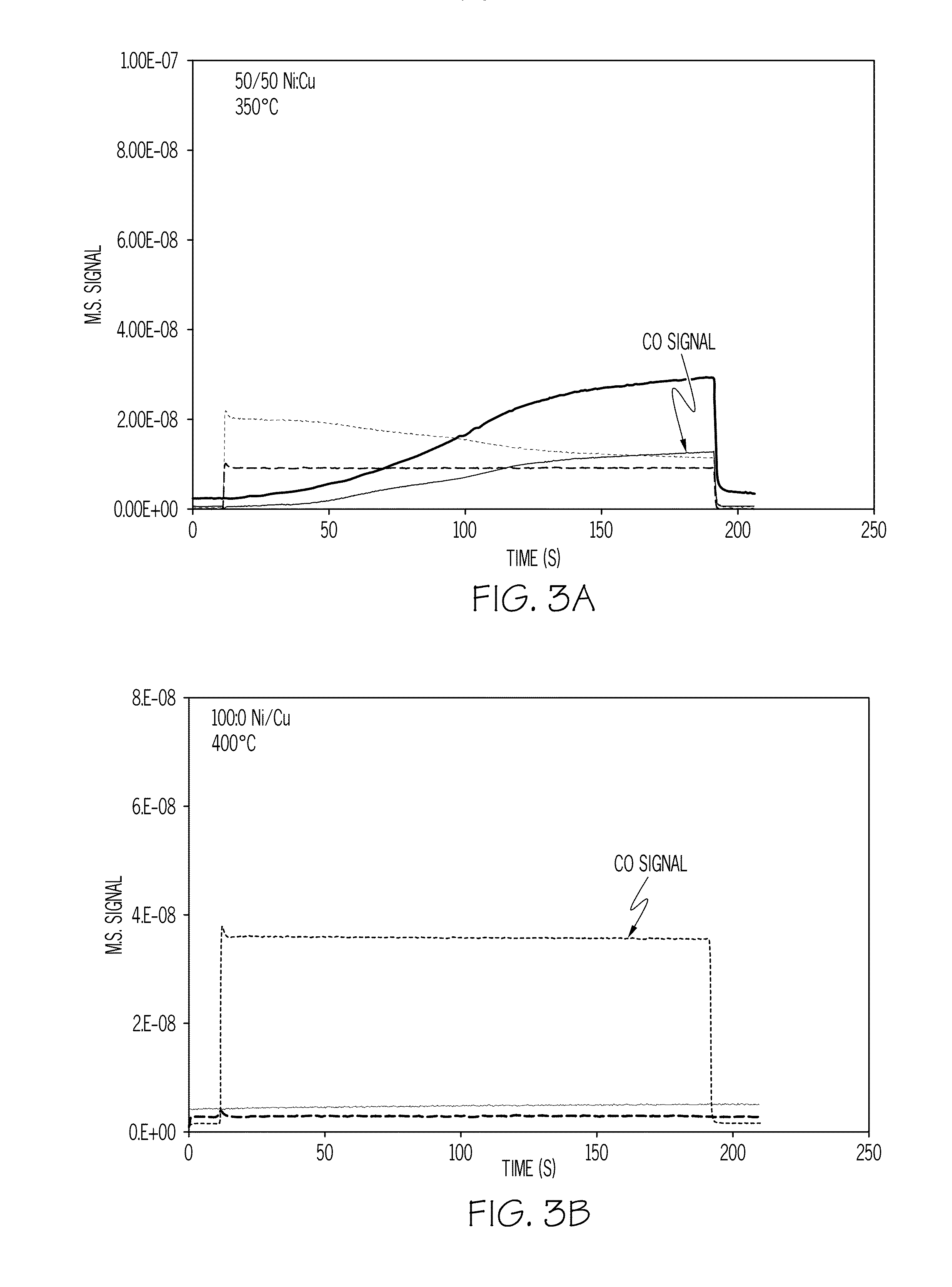
[0046]A catalyst sample loaded with 11 wt % of a nickel-copper mixture at a 1:1 Ni:Cu weight ratio was exposed to a simulated exhaust gas containing 1% CO in 10% H2O / N2 (volume %). As shown in FIG. 3A, the CO was completely removed at 350° C. A catalyst sample loaded with 12 wt % nickel (no copper) showed no CO conversion even at 400° C. under the same conditions as shown in FIG. 3B. As can be seen, the nickel-copper catalyst operates at lower temperatures and shows a greater rate of reduction / oxidation, which also indicates a greater OSC value.

example 2

[0047]A filter substrate comprised of cordierite in a column sized at 3 inches in length and 1 inch in diameter was dipped into a 6.50 ml well-mixed solution of nickel and copper. The concentration of nickel was 2.51×10⁻² g. per gram solution and the concentration of copper was also 2.51×10⁻² g. per gram solution. After dipping, the filter substrate was turned upside down and dipped into a 6.0 ml well-mixed solution of nickel and copper with the same concentrations described above. After soaking up the solution, the filter substrate was placed into an oven at 150° C. for 30 minutes. The dried filter was then calcined in a furnace at 600° C. for 1 hour. The resulting filter (Filter A) contained 5.3 wt % nickel-copper having a Ni:Cu weight ratio of 1:1.

example 3

[0048]A filter substrate comprised of cordierite in a column sized at 3 inches long and 1 inch diameter was dipped into a 6.50 ml solution of well mixed nickel and copper. The concentration of copper was 5.505×10⁻² g. nickel per gram solution and 5.499×10⁻² g copper per gram solution. After dipping, the wetted filter was inserted into a flow of 5 liter air per minute at 225° C. for 20 minutes. After this drying process, the other end of the filter was dipped into a 6.00 ml solution containing well mixed 5.505×10⁻² g. nickel and 5.499×10⁻² g copper per gram solution. The wetted filter was again inserted into a flow of 5 liter air per minute at 225° C. for 20 minutes. The dried sample was heated in air at a rate of 5° C. / min. to 600° C. then held at 600° C. for 1 hour. The resulting filter (Ni—Cu Filter) contained 10.3 wt % of nickel-copper having a weight ratio of 1:1.

[0049]FIG. 4 illustrates the oxygen-storage-capacity (OSC) of the Ni—Cu Filter in comparison with filters containing ...


PUM

PropertyMeasurementUnit
temperatureaaaaaaaaaa

Abstract

A particulate filter for use in a vehicle engine exhaust is provided which includes a catalyst containing a mixture of nickel and copper. The catalyst is impregnated into the filter substrate, which is non-reactive with nickel and copper. When used in a vehicle exhaust gas treatment system, the catalyst on the filter improves soot burn-off at low temperatures, provides improved efficiency in reducing CO and NOx emissions over the use of conventional three-way-catalyst washcoats, and provides enhanced oxygen storage capacity (OSC) and water-gas-shift (WGS) functions.

Description

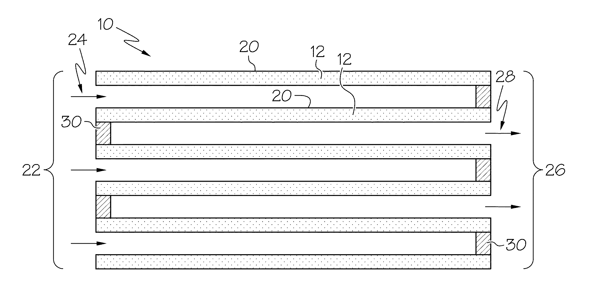
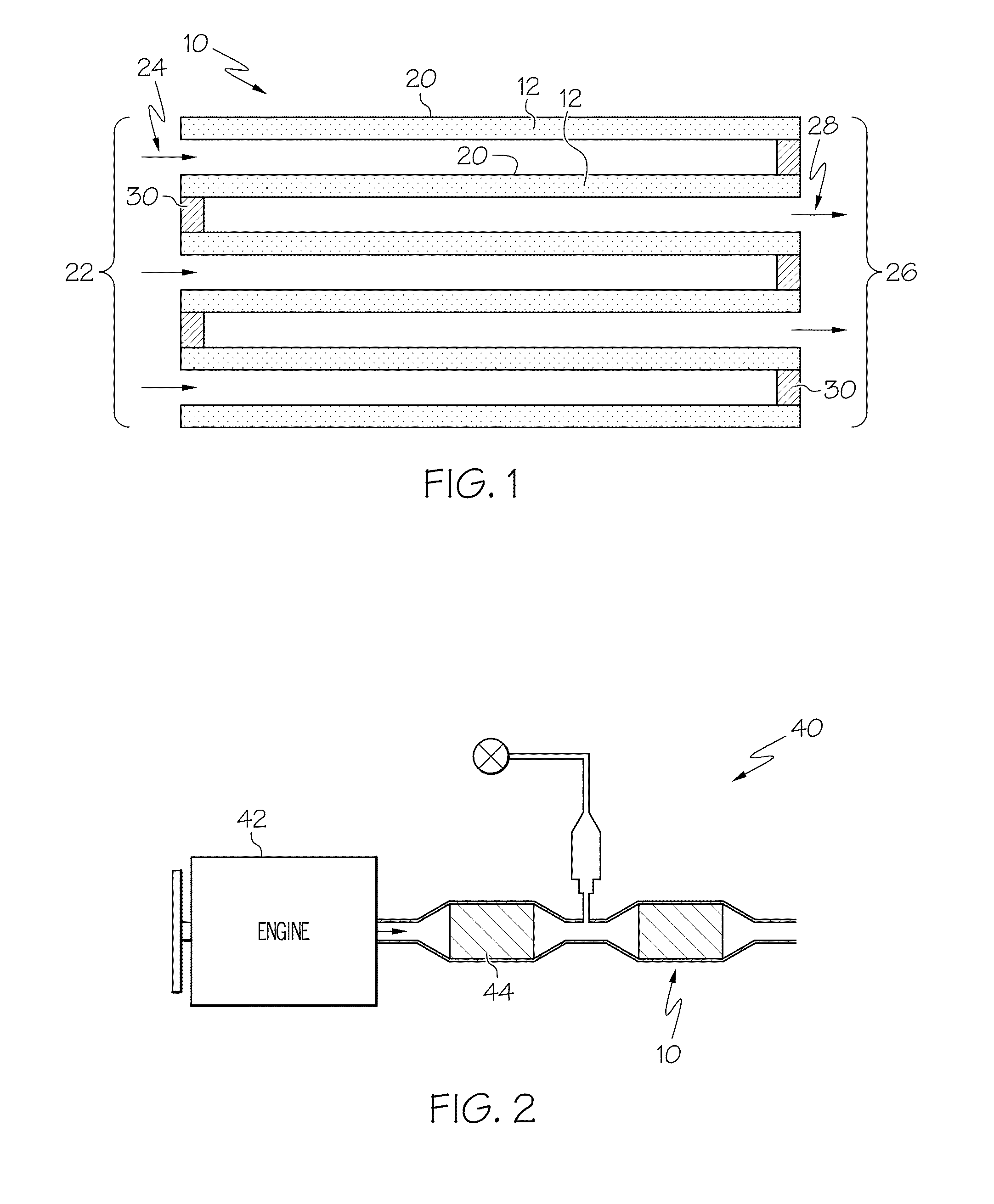
BACKGROUND OF THE INVENTION[0001]Embodiments described herein relate to a particulate filter for capturing particulates in the exhaust of a gasoline or diesel engine, and more particularly, to a particulate filter including a catalyst comprising a mixture of nickel and copper.[0002]In recent years, government regulations in the United States have restricted particulate emissions, which has necessitated improvements in the removal of particulates from diesel and gasoline engine emissions. Such particulates generally consist of carbonaceous particulates in the form of soot. Currently, the most commonly used method for removing soot from engine exhaust is the use of a particulate filter positioned in the engine exhaust which collects soot while allowing exhaust gases to pass through. The collected particulate matter is then burned off (oxidized) at elevated temperatures to clean and regenerate the filter. Regeneration of the deposited particulates must occur in order to prevent the fil...

Claims


Application Information

Patent Timeline
Patent Type & Authority Applications(United States)
IPC IPC(8): B01D53/94
CPCB01D53/94B01D53/945B01D2255/20753B01D2255/20761B01D2255/65B01D2255/908B01D2258/012B01J23/755Y02A50/20Y02T10/12
Inventor WARNER, JAMES ROBERTDOBSON, DOUGLAS ALLENJEN, HUNGWENCAVATAIO, GIOVANNI
Owner FORD GLOBAL TECH LLC
Learn More