Battery, battery pack, electronic apparatus, electric vehicle, electrical storage apparatus and electricity system

a battery pack and electric vehicle technology, applied in the field of batteries, can solve the problems of increased inner resistance, difficult to achieve high-power, and unfavorable production of electric vehicles, and achieve the effect of high capacity and high power of batteries

Active Publication Date: 2014-12-04
MURATA MFG CO LTD
View PDF1 Cites 46 Cited by
  • Summary
  • Abstract
  • Description
  • Claims
  • Application Information

AI Technical Summary

Benefits of technology

[0009]According to the present disclosure, it is possible to achieve both high capacity and high power of a battery.

Problems solved by technology

Therefore, a separator which has unequal conductivity may generate overvoltage due to a local imbalance in the current density.
Consequently, there are some cases where it is difficult to achieve high-power.
In such separators, uniformity of the treatment may be a significant factor; in cases where the treatment is performed non-uniformly, the resulting separator would have unequal conductivity, which leads to an increase in inner resistance and makes it difficult to achieve high-power.
Therefore, unless a suitable separator is selected, the lithium ions discharged from the positive electrode may not be well-spread on the surface of the negative electrode.
Since this leads to an increase in inner resistance, it would be difficult to realize both high capacity and high power at the same time.
It should be noted that a lithium cobalt oxide (LiCoO2) and other composite oxides that contain cobalt, have a layer structure but do not substantially contain nickel, may not be suitable for high power use; because of their characteristics of generating a large amount of heat during high-load discharge.
Therefore, it is desirable to employ a separator having a predetermined structure according to an embodiment of the present disclosure; or otherwise, it might have led to an increase in inner resistance, which would make it difficult to realize both high capacity and high power at the same time.

Method used


Image

  • Battery, battery pack, electronic apparatus, electric vehicle, electrical storage apparatus and electricity system
  • Battery, battery pack, electronic apparatus, electric vehicle, electrical storage apparatus and electricity system
  • Battery, battery pack, electronic apparatus, electric vehicle, electrical storage apparatus and electricity system

Examples


first embodiment

1. First Embodiment

Technical Background

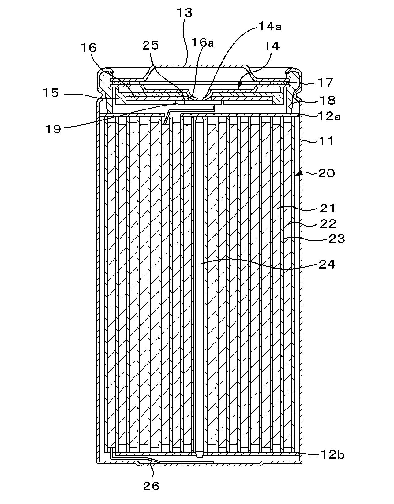
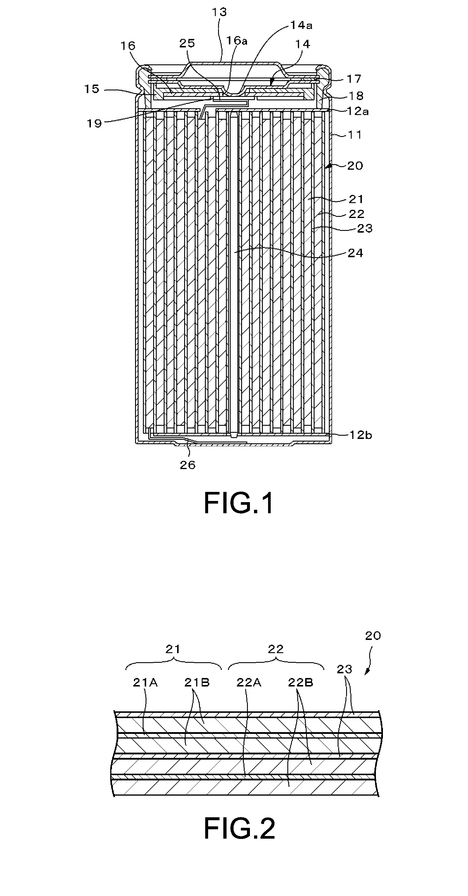
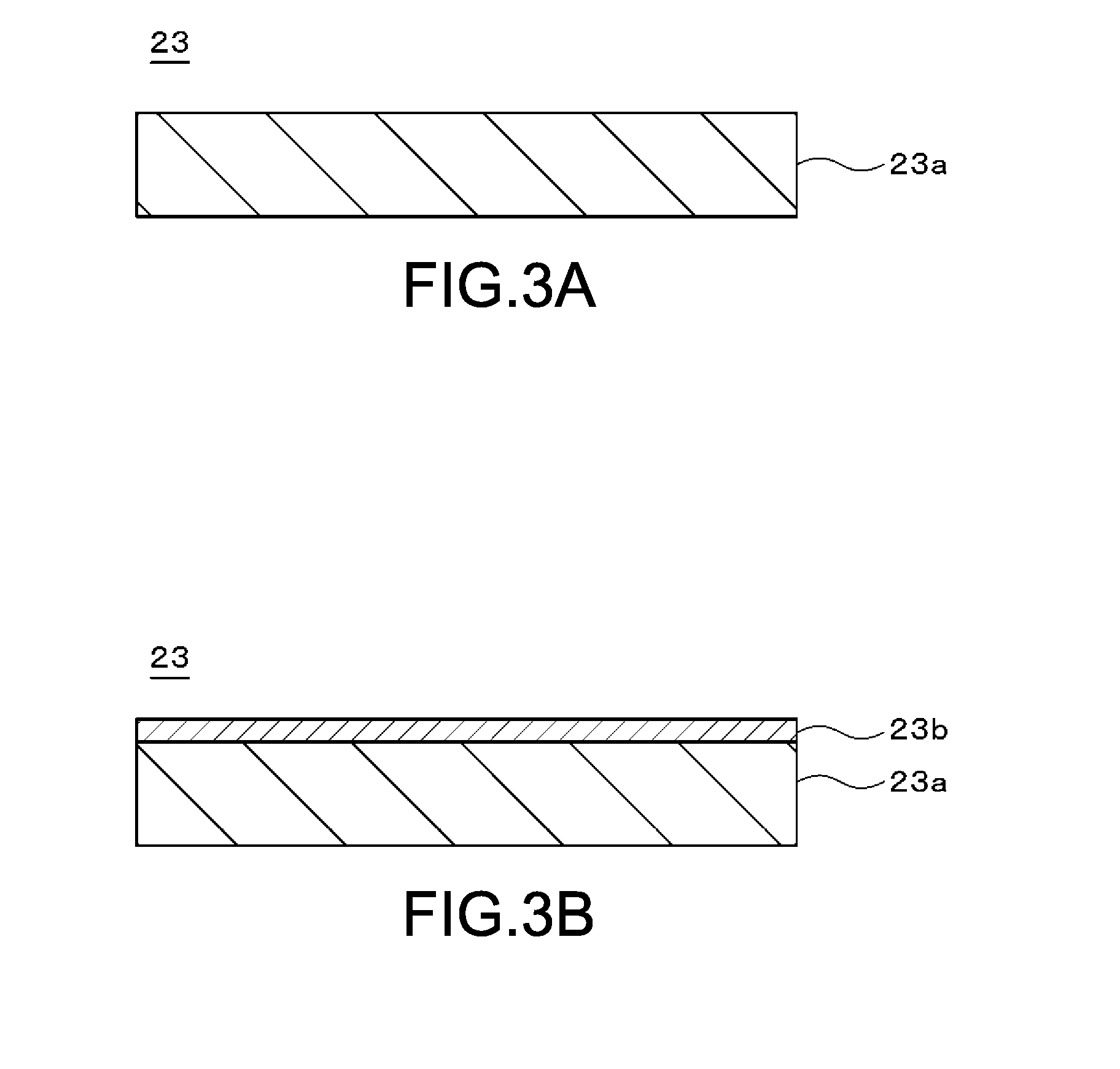
[0037]First, to facilitate understanding of the present disclosure, a technical background related to the present disclosure will be described. For example, in order to realize high capacity and high power of a battery such as a lithium-ion secondary battery with a rated size such as 18650-type (diameter of 18 mm and length of 65 mm); the greater the current density, the greater the total amount of lithium ions moving through fine pores of a separator per unit time (that is, an amount of electricity).

[0038]The movement of lithium ions in a system where the current density has become relatively large will take place dominantly in a part with the lowest transfer resistance. Therefore, a separator which has unequal conductivity may generate overvoltage due to a local imbalance in the current density. The generation of overvoltage would cause decomposition of an electrolyte solution which may give rise to a coating and result in an increase in inne...

second embodiment

2. Second Embodiment

[0160][Example of Battery Pack]

[0161]FIG. 4 is a block diagram showing a circuit configuration example of a case where the battery of the first embodiment of the present disclosure (hereinafter also referred to as “secondary battery”, as appropriate) is applied to a battery pack. The battery pack includes an assembled battery 301, an exterior, a switch unit 304 having a charge control switch 302a and a discharge control switch 303a, a current sensing resistor 307, a temperature sensing device 308, and a control unit 310.

[0162]Further, the battery pack includes a positive terminal 321 and a negative terminal 322. In charging, the positive terminal 321 and the negative terminal 322 are connected to a positive terminal and a negative terminal of a charger, respectively, and the charging is carried out. On the other hand, when using an electronic apparatus, the positive terminal 321 and the negative terminal 322 are connected to a positive terminal and a negative ter...

third embodiment

3. Third Embodiment

[0173]The above-mentioned battery according to the first embodiment of the present disclosure and the battery pack according to the second embodiment using this battery can be installed or be used in providing electricity to apparatus such as electronic apparatus, electric vehicle and electrical storage apparatus, for example.

[0174]Examples of electronic apparatus are laptops, PDA (Personal Digital Assistant), cellular phones, cordless telephone handset, video movies, digital still cameras, electronic books, electronic dictionaries, music players, radio, headphones, game machine, navigation system, memory cards, pacemakers, hearing aids, electric tools, electric shavers, refrigerator, air-conditioner, televisions, stereos, water heater, microwave oven, dishwasher, washing machine, dryer, lighting equipment, toys, medical equipment, robots, load conditioners, traffic lights, and the like.

[0175]Examples of electric vehicles are railway vehicles, golf carts, electric...


PUM

PropertyMeasurementUnit
thicknessaaaaaaaaaa
thicknessaaaaaaaaaa
layer structureaaaaaaaaaa

Abstract

There is provided a battery including a positive electrode, a negative electrode, a separator at least including a porous film, and an electrolyte. The positive electrode includes a positive electrode current collector having a pair of surfaces, and a positive electrode active material layer provided on each of the surfaces of the positive electrode current collector. The positive electrode active material layer contains a positive electrode active material. The positive electrode active material layer has an area density S [mg/cm2] more than or equal to 30 mg/cm2. The porous film included in the separator has a porosity ε [%] and an air permeability t [sec/100 cc] which satisfy a predetermined formula.

Description

CROSS REFERENCES TO RELATED APPLICATIONS[0001]The present application claims priority to Japanese Priority Patent Application JP 2013-116059 filed in the Japan Patent Office on May 31, 2013, the entire content of which is hereby incorporated by reference.BACKGROUND[0002]The present disclosure relates to a battery, a battery pack, an electronic apparatus, an electric vehicle, an electrical storage apparatus and an electricity system.[0003]There has been a growing demand for secondary batteries such as lithium-ion secondary batteries having high performance. Enhancement of battery characteristics including high capacity and high power has been demanded. For example, some technologies related to a separator of a secondary battery have been disclosed in Japanese Patent Application Laid-Open Nos. 2001-68088 and 2008-152985 (hereinafter referred to as “Patent Document 1” and “Patent Document 2”, respectively); and some technologies related to secondary batteries with high power have been ...

Claims


Application Information

Patent Timeline
Patent Type & Authority Applications(United States)
IPC IPC(8): H01M4/131B60L11/18B60L50/15H01M50/406H01M50/449H01M50/451H01M50/491
CPCH01M4/131H01M2004/028B60L11/1809B60L11/1851H01M4/136H01M4/525B60L53/00B60L58/10H01M10/052H01M10/425H01M10/486H01M2200/106H01M2220/20H01M2200/20H01M2004/021H01M50/46H01M50/451H01M50/406H01M50/491H01M50/449Y02T10/7072Y02T90/14B60L53/52B60L53/51Y02E60/10Y02T10/70Y02T90/12Y02P70/50H01M4/505H01M4/5825H01M50/463H01M50/414H01M2220/30H01M2220/10
Inventor ABE, TOMOHIROSUZUKI, MOTOMI
Owner MURATA MFG CO LTD
Why Eureka
Try Eureka