
Device for collecting body fluids

Inactive Publication Date: 2014-12-11
JUVIC INC
View PDF3 Cites 15 Cited by
  • Summary
  • Abstract
  • Description
  • Claims
  • Application Information

AI Technical Summary

Benefits of technology

The present invention is a device that can extract body fluids (such as blood) from humans with minimal damage and increased efficiency. It is easy to use, portable, and can effectively analyze the fluid after extraction. Overall, this invention provides a better way to extract fluids from subjects.

Problems solved by technology

The deficiency in pain due to bigger diameter of hypodermic needles and immunization reaction has been the main problem in the development of real-time blood analysis systems such as ubiquitous healthcare, point of care and health monitoring device.
While the length of silicon microneedle is not viable for blood extraction, it is required to reach into the deeper layers of the dermis at around 1500 um to be in touch with the blood vessels and it also has the risks of breakage inside the skin.
Though some plastics and metals microneedles which are fabricated using the deep X-ray lithography of LIGA (Lithographie, Galvanoformung, and Abformung) technique [8] and sputtering deposition method [5] are also widely used in the blood extraction system, in comparison might be biocompatible and have a good stiffness, the way of fabrication is too complicated and costly to mass-produce.
However, the blood extraction flow rate of the piezoelectric and electrolysis drive micropumps is too slow and fabrication are complicated.
SMA actuators not only needs a long cooling time but also their response time is too slower than other micropump actuators and the most important is the bigger size not suitable for disposal.
All the reported micropumps need the external power source and they were also costly with complicated fabrication method.
On the other hand, it is difficult for the vacuum drive system to transport the blood sample to other analysis devices.
Many factors make these blood extraction devices not suitable for disposal and single uses by patients.

Method used


Image

  • Device for collecting body fluids
  • Device for collecting body fluids
  • Device for collecting body fluids

Examples


example 1

Fabrication of Hollow Microneedle for Minimally Invasive Blood Extraction

[0061]A solid microneedle was fabricated by using SU-8 2050 photoresist (purchased from Microchem) having a viscosity of 14,000 cSt. The SU-8 2050 negative photoresist was coated onto metal and silicon substrates to 1000 μm and 2000 μm, respectively, and then kept at 120 for 5 minutes to maintain fluidity of SU-8. The photoresist was then placed in contact with a prepared 3×3 pattern frame having a diameter of 200 μm. While the temperature of the substrate was slowly lowered to 70 to 60, the coated SU-8 2050 photoresist has such a viscosity that it can be lifted. Here, the lifting frame was lifted at a speed of 10 μm / s for 5 minutes, thereby fabricating an initial solid structure of 3,000 μm. The formed initial solid structure may be separated from the lifting frame by increasing the speed of a second lifting or performing a cutting process. As a result, the initial coating thickness of 1,000 μm resulted in a s...

example 2

Blood Extraction Using Hollow Microneedle for Minimally Invasive Blood Extraction

[0064]Influence of Change in Inner Diameter of Hollow Microneedle at the Time of Actual Blood Extraction

[0065]The syringe was placed vertically on the syringe pump. A pressurizer was connected to the end of the syringe, and then slowly drawn to produce a negative pressure. Then, the negative pressures at a predetermined volume were measured by a pressure gauge. The average thereof was obtained and then determined as the standard of a negative pressure. Under the conditions of the same negative pressure (P=15.44 kPa), the blood extraction volumes by hollow microneedles with various sized inner diameters were measured (Table 1). As a result of experiment, blood was not able to be extracted due to a blockage phenomenon when the inner diameter was 50 μm or smaller. The blockage phenomenon was significantly reduced when the inner diameter was 70 μm, and the blockage phenomenon did not occur when the inner di...

example 3

Fabrication of Device for Fluid Extraction (Blood Extraction)

[0070]Principle of Device for Blood Extraction of Present Invention

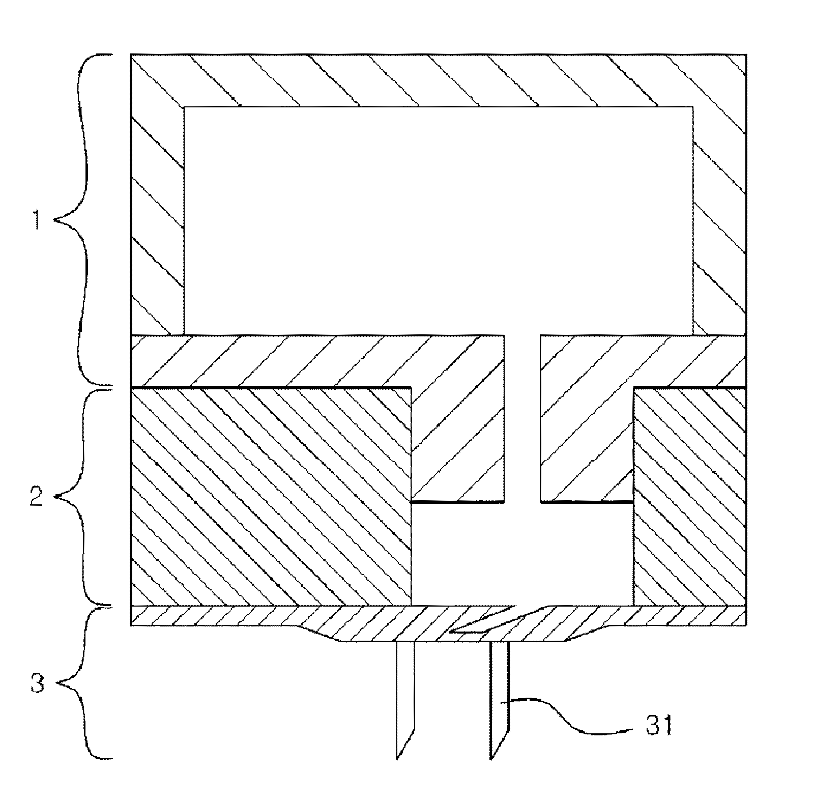
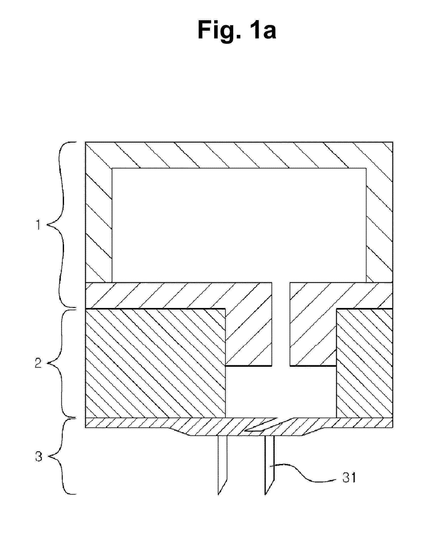
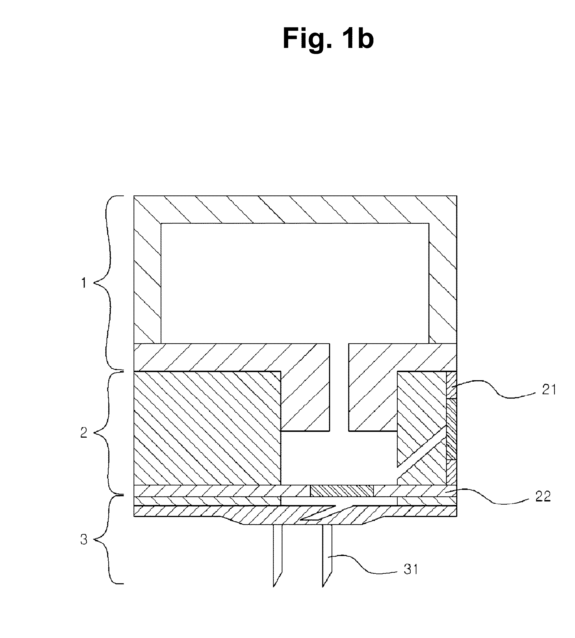
[0071]The present inventors developed a painless and portable device for blood extraction (height: 11 mm, width: 11 mm). The device for blood extraction of the present invention is largely composed of three parts (see: FIG. 1b). (a) an internal pressure regulator (1) made of a highly elastically deformable material (e.g., PDMS) and producing a negative pressure for extracting a blood sample; (b) a fluid reservoir 2 (preferably made of PDMS) equipped with two passive check valves (an inlet valve 21 and an outlet valve 22) for controlling the blood sample to be extracted and transported to another part; and (c) a perforator 3 connected to the fluid reservoir 2 and disposed at a lower portion of the device, the perforator 3 including a minimally invasive hollow microneedle 31 for forming a hole in the body.

[0072]The device for blood extraction of the present i...


PUM


Abstract

The present invention relates to a device for collecting body fluids, the device comprising: (a) an internal pressure adjustment means for adjusting the internal pressure of the device, and the internal pressure adjustment means has an internal space and is made of an elastic deformable material; (b) a fluid accommodation means, which is openly connected to the internal pressure adjustment means, for accommodating body fluids collected from the human body; and (c) a perforation means which is connected to the fluid accommodation means, is located at the lower part of the device, and comprises a hollow microstructure for forming an opening on the body.

Description

TECHNICAL FIELD[0001]The present invention relates to a device for extraction of body fluids.BACKGROUND ART[0002]The blood is one vital fluid in the human body and plays important roles in the general physiology of human beings. Blood analysis is used to obtain the information about blood physical and chemical properties to monitor human health state. For example, it is extremely important for diabetics to extract blood sample and measure blood glucose level in daily life for prevention and treatment of diabetes. Nowadays, the development of safe, automated and compact real-time systems for blood analysis become one of the most important research themes in the field of medical engineering.[0003]Through blood extraction to get the blood sample is the basic step of detection for diagnosis and remedy of various disease. Generally blood analysis is commonly performed on a blood sample from a vein in the arm using hypodermic needles or via finger-prick. The deficiency in pain due to bigg...

Claims


Application Information

Patent Timeline
IPC IPC(8): A61B5/151A61B5/15
CPCA61B5/15113A61B5/150396A61B5/150221A61B5/150099A61B5/1411A61B5/150022A61B5/150969A61B5/150984A61B5/15142A61B5/1405A61B5/157A22B5/04
Inventor JUNG, HYUNG ILLI, CHENGGUOLEE, CHANG YOELLEE, KWANG
Owner JUVIC INC
Learn More