Power supply device and components thereof

a power supply device and power supply technology, applied in the direction of electrical apparatus construction details, electronic circuit testing, instruments, etc., can solve the problems of higher switching losses, higher losses in ferrite components, and known psus not providing overt spatial partitioning of switching partitions, etc., to achieve effective noise reduction, reduce noise, and improve the effect of prognosis

Active Publication Date: 2014-12-18
SPECTRALWATT PTY LTD
View PDF13 Cites 22 Cited by
  • Summary
  • Abstract
  • Description
  • Claims
  • Application Information

AI Technical Summary

Benefits of technology

[0026]Various embodiments are advantageous in providing or facilitating a self monitoring function of the power supply device and / or components thereof, for example by providing more effective noise reduction and allowing measurement of internal parameters allowing prognosis calculation of serviceability.
[0027]Various embodiments also provide other advantages including, for example, lower noise, faster testing in manufacture, faster assembly, self diagnosis and / or providing serviceability information to a network when deployed for use.

Problems solved by technology

Known PSUs do not provide overt spatial partitioning of a switching partition, for example, from control, magnetic or capacitive electronics.
However, such higher frequencies also incur deleterious coupling between components, higher switching losses and greater losses in the ferrite components.
Also higher frequency switching in known PSUs may violate regulatory Electro Magnetic Compatibility standards (EMC).
In known PSU devices, to avoid crosstalk and electromagnetic interference between components, spatial separation within this plane between components is generally relied upon, thus leading to a relatively large area and consequently large sized devices.

Method used


Image

  • Power supply device and components thereof
  • Power supply device and components thereof
  • Power supply device and components thereof

Examples


Embodiment Construction

[0042]The following modes, given by way of example only, are described in order to provide a more precise understanding of the subject matter of a preferred embodiment or embodiments.

[0043]In the figures, incorporated to illustrate features of example embodiments, like reference numerals are used to identify like parts throughout the figures.
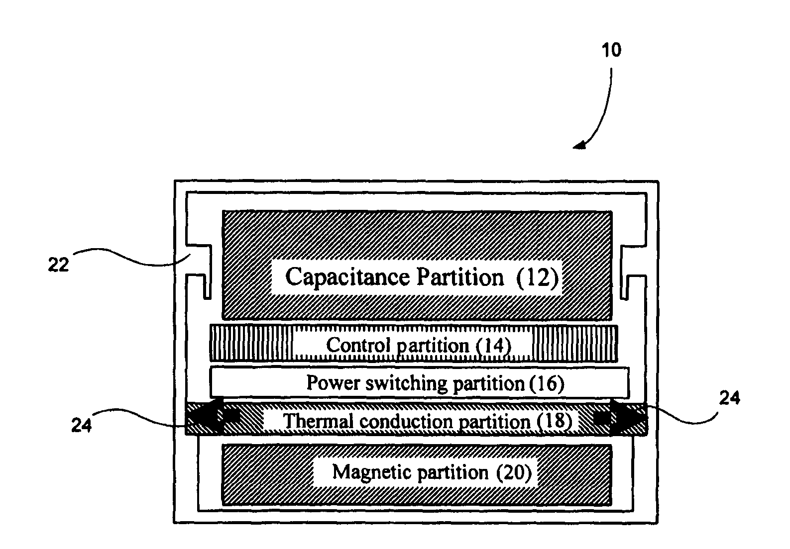
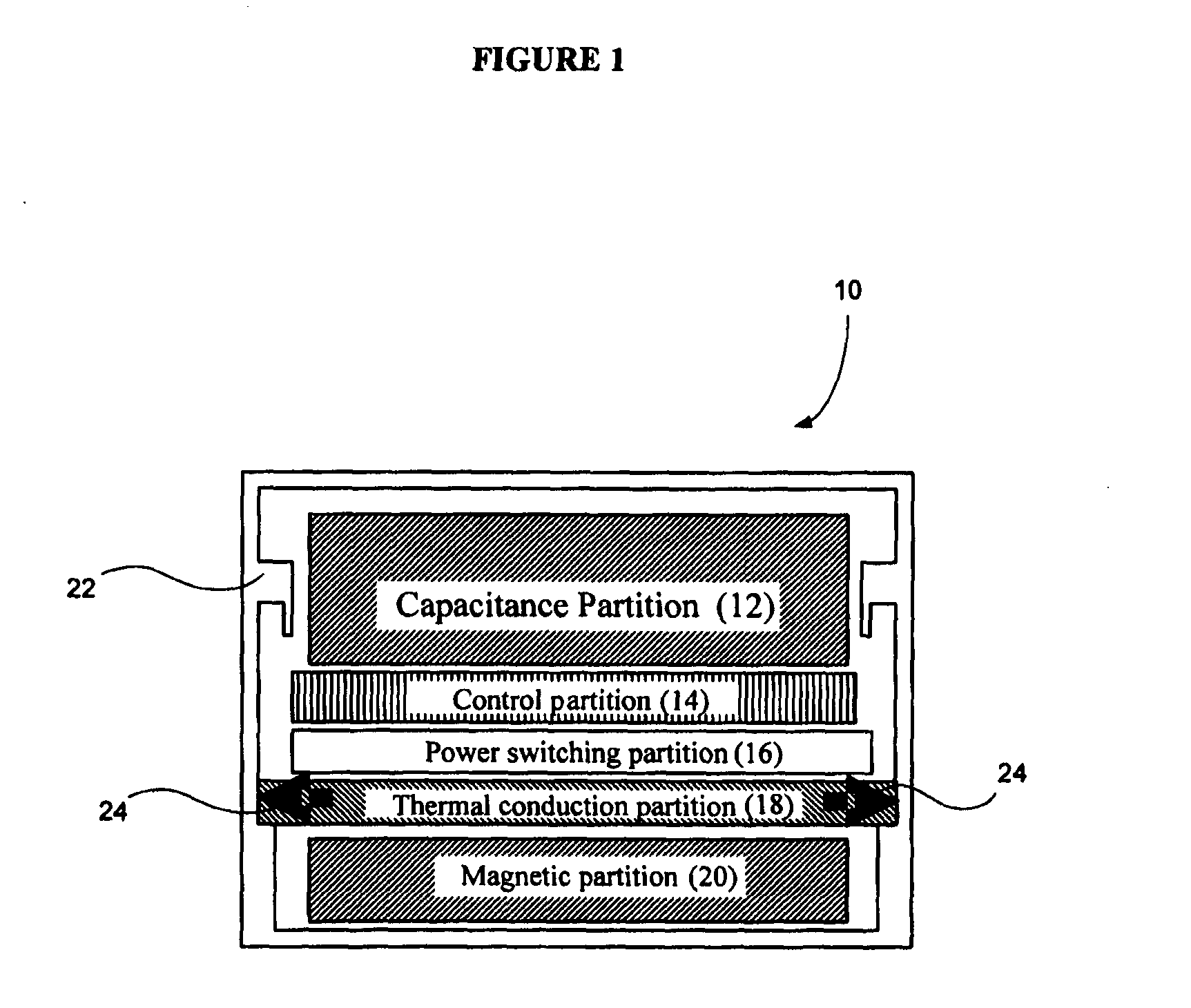
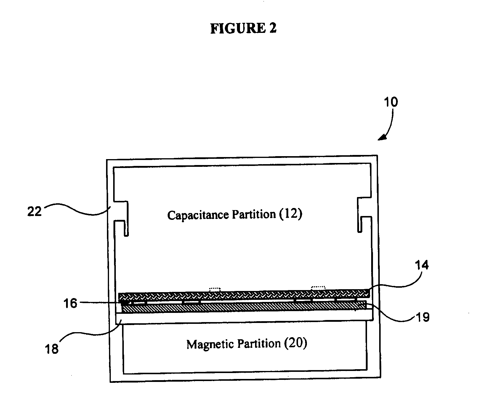
Power Supply Device

[0044]A preferred embodiment of the present invention is now described. This embodiment describes the use of an example electrical conversion device, where an input power of voltage and current is converted into one or more outputs of voltage and current but of less total output power due to conversion loss. The physical structure described herein is inherently suitable for a variety of alternate embodiments.

[0045]The topology used is optimised for minimum size and power density with extended Power Fail Early Warning (PFEW). A general description of the electronic topology is of a Constant Current Mode PFC and Asymmetric Half ...


PUM

PropertyMeasurementUnit
temperaturesaaaaaaaaaa
lengthaaaaaaaaaa

Abstract

A power supply device including a capacitance partition, a control partition, a power switching partition, a thermal conduction partition, a magnetic partition. The thermal conduction partition includes electrical connections to connect other partitions. The thermal conduction partition provides for magnetic shielding of the magnetic partition and thermal dissipation in a substantially orthogonal direction to the electrical connections. The layering arrangement allows automated production and/or testing.

Description

TECHNICAL FIELD[0001]The present invention generally relates to power supply units or devices, and components thereof, for providing power to electronic devices. More particularly, various alternate aspects generally relate to a power supply unit or device provided with partitions or a layered structure, components thereof, for example a thermal conduction partition, a method of manufacturing or testing, and / or a transformer.BACKGROUND[0002]Presently known power supplies, for example Intel™ ATX specification compliant small power supplies, and other miniaturisation designs exemplified by the many varieties of DC-DC or AC-DC “Brick” Power Supply Units (PSU), have significant disadvantages. Known PSUs do not provide overt spatial partitioning of a switching partition, for example, from control, magnetic or capacitive electronics. Energy storage components are primarily larger capacitors, such as electrolytic capacitors which are required to be kept cool, and magnetic components are tr...

Claims


Application Information

Patent Timeline
Patent Type & Authority Applications(United States)
IPC IPC(8): H05K1/02H05K3/30H05K13/08H05K7/20
CPCH05K1/0203H05K7/2089H05K2203/163H05K13/08H05K3/30H05K3/0061H05K7/20518H05K7/209Y10T29/49004Y10T29/4913
Inventor WILLIAMS, DONALD VICTOR
Owner SPECTRALWATT PTY LTD
Why Eureka
Try Eureka