
Electrophotographic photoreceptor, method for manufacturing the photoreceptor, and electrophotographic apparatus including the photoreceptor

a photoreceptor and electrophotography technology, applied in the direction of electrographic process, instruments, corona discharge, etc., can solve the problems of increasing the transfer burden, increasing the difference in image density, and no satisfactory structures have been developed, and achieve excellent photoresponsivity, gas resistance and solvent crack resistance, and favorable environmental characteristics

Active Publication Date: 2014-12-18
FUJI ELECTRIC CO LTD
View PDF5 Cites 3 Cited by
  • Summary
  • Abstract
  • Description
  • Claims
  • Application Information

AI Technical Summary

Benefits of technology

The present invention is about a new way to make a photoreceptor for electrophotography that is more durable, sensitive, and has good electrical properties. By using a specific type of resin binder and a combination of specific additives, the resulting photoreceptor has better resistance to gas, solvents, and environmental factors. These improvements make it easier to produce and use the photoreceptor for electrophotography.

Problems solved by technology

In addition to the above, various studies on polycarbonate structures have been implemented to date for the purpose of enhancing wear resistance, but no satisfactory structures have been developed yet.
In color printers, stronger transfer currents have had to be used because a process of transferring overlapped toners and a transfer belt have been employed; thus, when performing printing on sheets of various sizes, the difference in transfer burden occurs between the paper sizes and between the sheets, resulting in an increase in the difference in image density.
In other words, in case of printing on a large number of small sheets, the photoreceptor portion through which the sheets do not pass (non-passage portion) is constantly under a direct impact of transfer, compared to the photoreceptor part through which the sheets pass (passage portion), increasing the transfer burden.
Due to this difference in transfer burden between the passage portion and the non-passage portion, a potential difference is generated in the developer when printing is performed subsequently on large sheets, creating a density difference.
Therefore, the conventional technologies, unfortunately, cannot sufficiently fulfill such demand.
When the photoreceptor is exposed to the ozone remaining or accumulating in the apparatus, the organic substances configuring the photoreceptor are oxidized, destroying the original structure and significantly deteriorating the properties of the photoreceptor.
Such degradation of the properties of the photoreceptor caused by the gas involves invasion of the outermost layer of the photoreceptor and an adverse effect caused by the gas flowing into the photosensitive layer.
However, the harmful gas flowing into the photosensitive layer can destroy the structures of the organic substances of the photosensitive layer.
Especially in a tandem system color electrophotographic apparatus using a plurality of photoreceptors, when gas affects the photoreceptors of the apparatus differently depending on where the photoreceptors are installed, fluctuations in color tones occur, interfering with proper generation of images.
Such degradation of the properties of the photoreceptor in a tandem system color electrophotographic apparatus, therefore, is a particularly critical issue.
In some cases, the surface of the photoreceptor is contaminated by ozone, nitrogen oxides and the like that are generated at the time of charging the photoreceptor.
When this happens, there are problems such as image bleeding due to the contaminants themselves, a decrease in lubricity of the surface of the photoreceptor caused by adhering materials, easy adhesion of paper dust and toner, squealing and peeling of the blade, and the susceptibility of the surface to scratches.
Japanese Patent Application Publication Nos. 2004-354759 and H4-179961 (Patent Documents 2 and 3), for example, each propose polycarbonate resin having a specific structure, but do not take into enough consideration the compatibility between various charge transport materials and additives, as well as the solubility of the resin.
However, resin with a bulky structure has a lot of spaces between polymers, and, for example, discharged substances upon charging, contact members, or foreign matters may easily penetrate into the photosensitive layer, hence it difficult to obtain sufficient durability.
H3-273256 (Patent Document 5) proposes polycarbonate having a special structure that is configured to improve printing durability and coatability, but does not provide enough description of a charge transport material or an additive to be combined, bringing about a problem in which stable electric properties cannot be maintained when the apparatus is used for a long time.
These patent documents, however, do not take into enough consideration resin binders or additives to be combined with the charge transport materials, and it has not been possible yet to comply with a change in operating environments, maintain the electrical properties of the photoreceptors used for a long time, improve wear resistance, and mainten contamination resistance.
Unfortunately, the reality is that these technologies cannot obtain a photoreceptor having sufficient gas resistance or cannot accomplish satisfactory results regarding the electrical properties such as responsivity, image memories, and potential stability at the time of printing, depending on the combination of resin and the charge transport material, even if satisfactory characteristics are exercised for the gas resistance.
Unfortunately, the technologies described in these patent documents are not satisfactory in all aspects of electrical properties such as photoresponsivity, wear resistance, solvent crack resistance and the like.

Method used


Image

  • Electrophotographic photoreceptor, method for manufacturing the photoreceptor, and electrophotographic apparatus including the photoreceptor
  • Electrophotographic photoreceptor, method for manufacturing the photoreceptor, and electrophotographic apparatus including the photoreceptor
  • Electrophotographic photoreceptor, method for manufacturing the photoreceptor, and electrophotographic apparatus including the photoreceptor

Examples


example 1

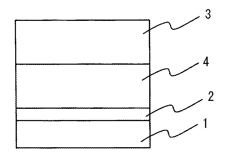
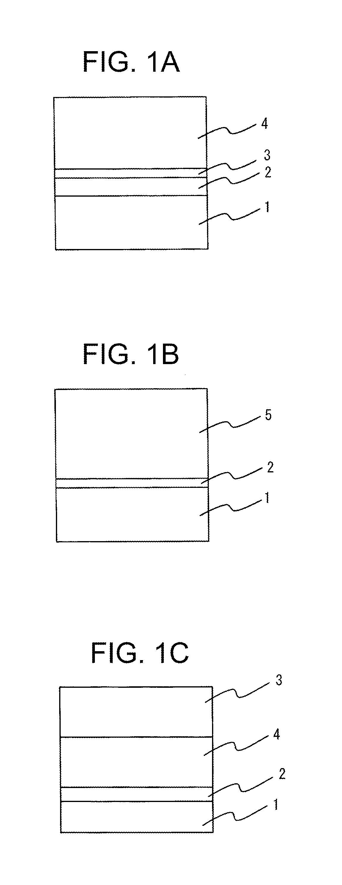
[0069]An alcohol-soluble nylon (manufactured by Toray Industries, Inc., trade name: “CM8000”) in an amount of 3 parts by mass and aminosilane-treated titanium oxide fine particles in an amount of 7 parts by mass were dissolved and dispersed in 90 parts by mass of methanol, thus preparing coating liquid A. This coating liquid A was immersion-coated on the outer circumference of an aluminum cylinder having an outer diameter of 30 mm, which is formed as a conductive substrate 1. The coating liquid on this cylinder was dried at 100° C. for 30 minutes, to obtain an undercoating layer 2 having a film thickness of 3 μm.

[0070]Y-type titanyl phthalocyanine in an amount of 1 part by mass as a charge generating material and a polyvinyl butyral resin (manufactured by Sekisui Chemical Co., Ltd., trade name: “S-LEC KS-1”) in an mount of 1.5 parts by mass as a resin binder were dissolved and dispersed in 60 parts by mass of dichloromethane, thus preparing coating liquid B. This coating liquid B wa...

example 2

[0072]A photoreceptor was produced by the same method as the one used in Example 1, except that the additive expressed by the chemical formula (6-1) that was used in Example 1 was replaced with the additive expressed by the chemical formula (6-2).

example 3

[0073]A photoreceptor was produced by the same method as the one used in Example 1, except that the molecular weight of the resin (1) that was used in Example 1 was changed to 50,000 and that the amount of the additive to 0.2 parts by mass.


PUM

PropertyMeasurementUnit
thicknessaaaaaaaaaa
thicknessaaaaaaaaaa
thicknessaaaaaaaaaa

Abstract

A photoreceptor for electrophotography includes a photosensitive layer provided on a conductive substrate that contains at least a resin binder, a charge transport material, and an additive. The photoreceptor exhibits high photoresponsivity, stable electrical properties regardless of repeated use thereof, and high durability. The resin binder contains a polycarbonate resin composed of a copolymer having structural units expressed by general formulae (1) and (2) below. The charge transport material contains at least one type of stilbene compound expressed by general formulae (3), (4), and (5) below. The additive contains at least one type of diester compound expressed by general formula (6) below.

Description

CROSS-REFERENCE TO RELATED APPLICATION(S)[0001]This non-provisional application is a continuation of and claims the benefit of the priority of Applicants' earlier filed PCT Application No. PCT / JP2012 / 060784 filed Apr. 20, 2012, the entire contents of which are incorporated herein by reference.BACKGROUND OF THE INVENTION[0002]1. Field of the Invention[0003]The present invention relates to a photoreceptor for electrophotography (simply referred to as “photoreceptor,” hereinafter) for use in electrophotographic printers, copiers, facsimile machines and the like, a method for manufacturing the photoreceptor for electrophotography, and an electrophotographic apparatus. More particularly, the present invention relates to a photoreceptor for electrophotography that exhibits excellent wear resistance, photoresponsivity, and gas resistance by having a combination of a resin binder, a charge transport material, and an additive having specific structures, a method for manufacturing such photor...

Claims


Application Information

Patent Timeline
Patent Type & Authority Applications(United States)
IPC IPC(8): G03G5/06
CPCG03G5/0614G03G5/0564G03G5/0607G03G5/0609G03G5/0672G03G5/06147G03G5/043G03G5/047
Inventor ZHANG, QUANQIUSUZUKI, SHINJIROZHU, FENGQIANGTAKEUCHI, MASARU
Owner FUJI ELECTRIC CO LTD
Learn More