Liquefaction of Natural Gas

Inactive Publication Date: 2015-01-01
HOULDER
View PDF4 Cites 33 Cited by
  • Summary
  • Abstract
  • Description
  • Claims
  • Application Information

AI Technical Summary

Benefits of technology

[0021]Preferably, the method may further comprise delivering the further LNG to the at least one storage tank. Accordingly, the LNG that is created through the method may subsequently be used for condensing furth

Problems solved by technology

However, steam turbine propulsion is a relatively inefficient means to drive a large ship.
The diesel engine in such a ship is unable to handle BOG and instead an independent LNG re-liquefaction plant is provided on the vessel.
Furthermore, as well as high power requirements, the re-liquefaction plant is typically unable to handle high boil-off rates.
Excess BOG that the LNG re-liquefaction plant is unable to handle is burnt in a gas combustion unit (GCU) and thereby wasted.
As mentioned above, while this offers a potential method for handling BOG needed to provide propulsion and/or electricity, there remains the issue of handling such BOG when the required load

Method used


Image

  • Liquefaction of Natural Gas
  • Liquefaction of Natural Gas
  • Liquefaction of Natural Gas

Examples


Embodiment Construction

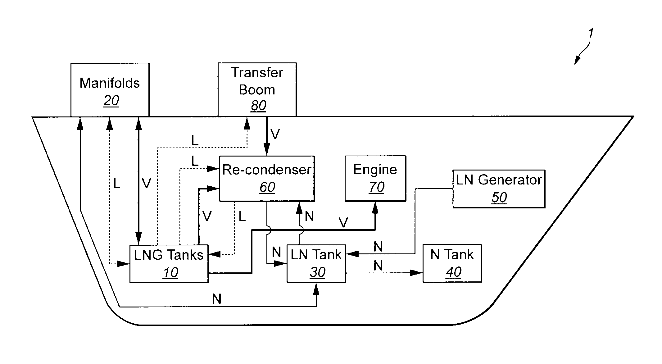
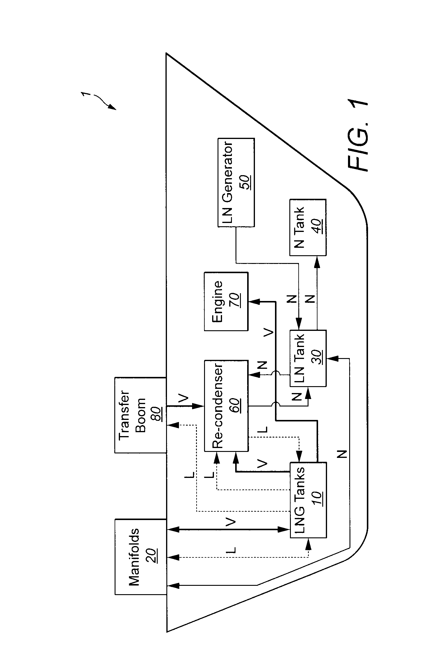
[0029]Referring to FIG. 1, a schematic diagram is provided showing the principle elements of a LNG handling system aboard a bunker vessel 1 for re-fuelling larger ships. The system comprises two LNG storage tanks 10, port and starboard manifolds 20, a liquid nitrogen tank 30, a gaseous nitrogen tank 40, a liquid nitrogen generator 50, a re-condenser unit 60, engines 70 and a flow boom 80. FIG. 1 illustrates functional connections between the various illustrated elements of the system for the transfer of LNG (indicated as “L”, dotted lines), natural gas vapour (indicated as “V”, thick lines) and nitrogen (both liquid and gaseous indicated as “N”, thin lines).

[0030]The port and starboard manifolds 20 are arranged to allow transfer of LNG, natural gas vapour, and nitrogen between the bunker vessel and an on-shore facility. LNG received from the port and starboard manifolds is stored in the storage tanks 10. In this embodiment, the storage tanks are pressurised, C-class, storage tanks w...


PUM


Abstract

A method and apparatus for liquefying natural gas vapour is provided. Firstly, liquid natural gas is sub-cooled at a first heat exchanger using a liquid coolant such as liquid nitrogen. The sub-cooled liquid natural gas is then used to condense the natural gas vapour at a second heat exchanger.

Description

FIELD OF THE INVENTION[0001]The present invention relates to liquefaction of natural gas vapour, particularly during the transport and storage of liquefied natural gas (LNG). In particular, but not exclusively, the present invention relates to the handling of boil off gas in a bunker vessel used to refuel LNG-powered vessels.BACKGROUND TO THE INVENTION[0002]Liquefied natural gas (LNG) is natural gas (typically methane—CH4) that has been liquefied, typically to make it more manageable during storage and / or transport. At atmospheric pressure, this means the temperature of the LNG is reduced to around −163 degrees centigrade or below.[0003]LNG carriers are vessels used to carry LNG across large distances, particularly to carry LNG from gas producing nations to gas consuming nations. The journey times of such vessels are significant, measured in days, weeks and even months. During such time, the LNG is stored at low temperature in order that it does not vaporise.[0004]Notwithstanding th...

Claims


Application Information

Patent Timeline
IPC IPC(8): F25J1/00
CPCF25J1/0022F25J1/0072F17C2221/033F17C2223/0161F17C2223/033F17C2225/044F17C2265/034F17C2265/066F17C2270/0105F25J1/0025F25J1/0204F25J1/0222F25J1/0234F25J1/0278F25J2210/42F25J2290/34F25J2290/62F17C5/00
Inventor EDWARDS, DAVID
Owner HOULDER
Why Eureka
Try Eureka