Using An LED Die To Measure Temperature Inside Silicone That Encapsulates An LED Array

Active Publication Date: 2015-01-01
SIGNIFY HLDG BV
View PDF6 Cites 41 Cited by
  • Summary
  • Abstract
  • Description
  • Claims
  • Application Information

AI Technical Summary

Benefits of technology

[0007]A light-emitting diode (LED) device includes first and second LED dies that both have the same structure and that are both encapsulated by a silicone layer. Driver circuitry supplies the first LED die with sufficient drive current to illuminate the first LED die. Control circuitry supplies the second LED die with a constant current, determines the voltage across the second LED die, and calculates the temperature of the second LED die based on the voltage across the second LED die. The LED drive current has a maximum magnitude t

Problems solved by technology

Moreover, LEDs have significantly longer lifetimes than both incandescent bulbs and fluorescent tubes.
However, the useful lifetime of LEDs is significantly reduced if the operating temperature exceeds certain limits.
First, the phosphor that converts blue light from the LED dies into longer wavelength light generates heat.
Second, a single LED die produces too little light to be used as a replacement for a conventional light source in most applications.
The large number of LED dies that are packaged in close proximity to one another under a transparent carrier material that contains phosphor particles results in a large amount of heat generated within a small volume.
The temperature under the transparent carrier material rises when the large amount of heat generated by the many LED dies cannot be conducted fast enough away from the LED device due t

Method used


Image

  • Using An LED Die To Measure Temperature Inside Silicone That Encapsulates An LED Array
  • Using An LED Die To Measure Temperature Inside Silicone That Encapsulates An LED Array
  • Using An LED Die To Measure Temperature Inside Silicone That Encapsulates An LED Array

Examples


Embodiment Construction

[0019]Reference will now be made in detail to some embodiments of the invention, examples of which are illustrated in the accompanying drawings.

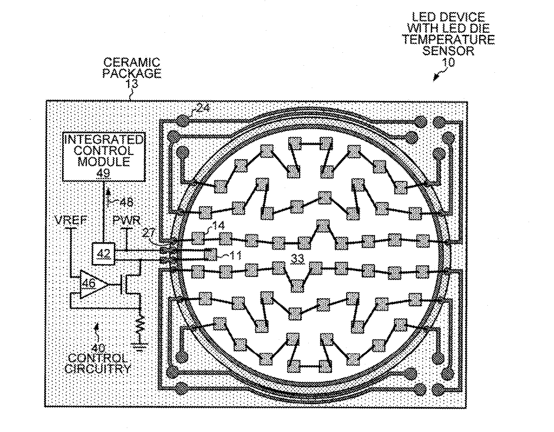
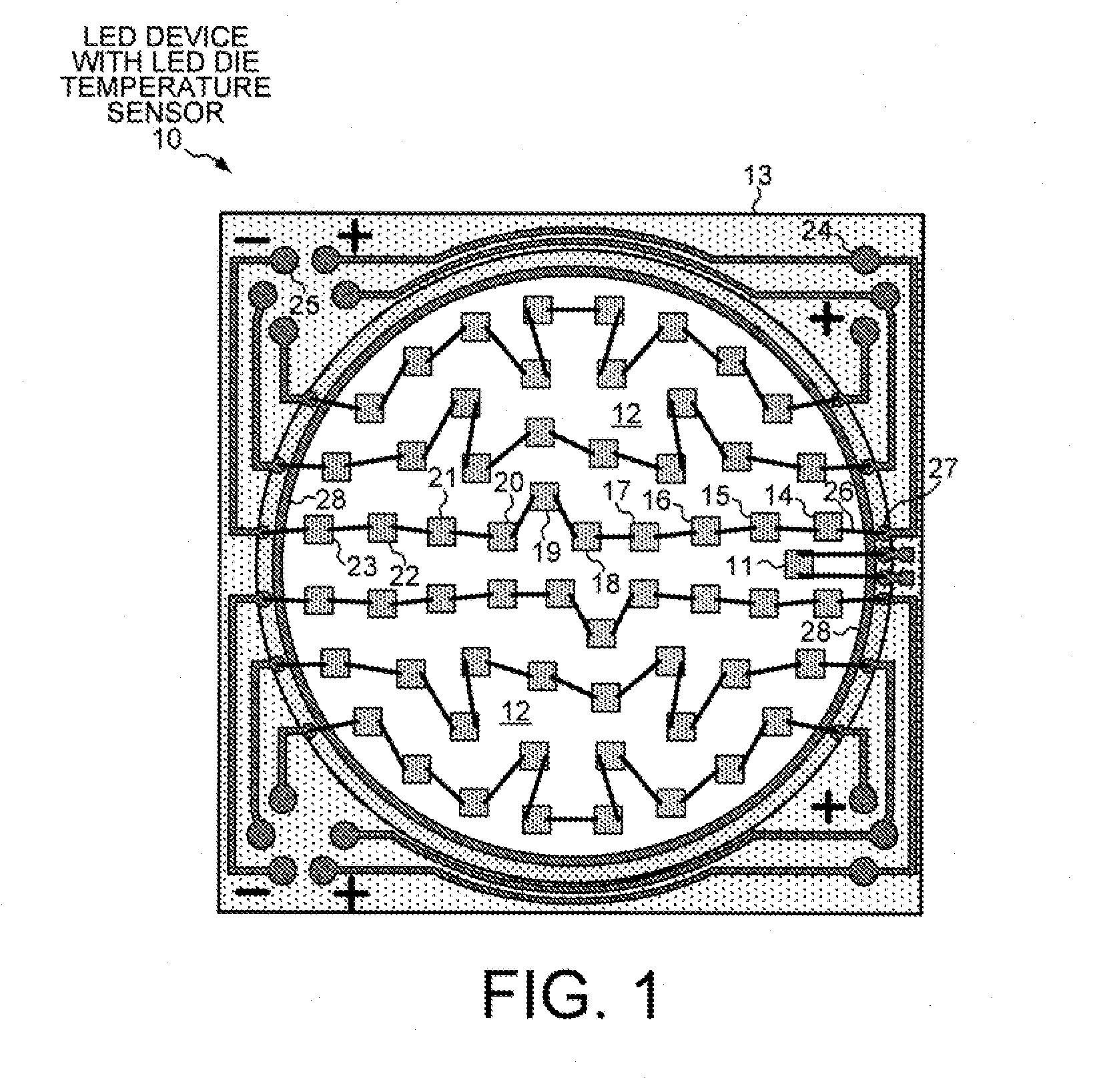
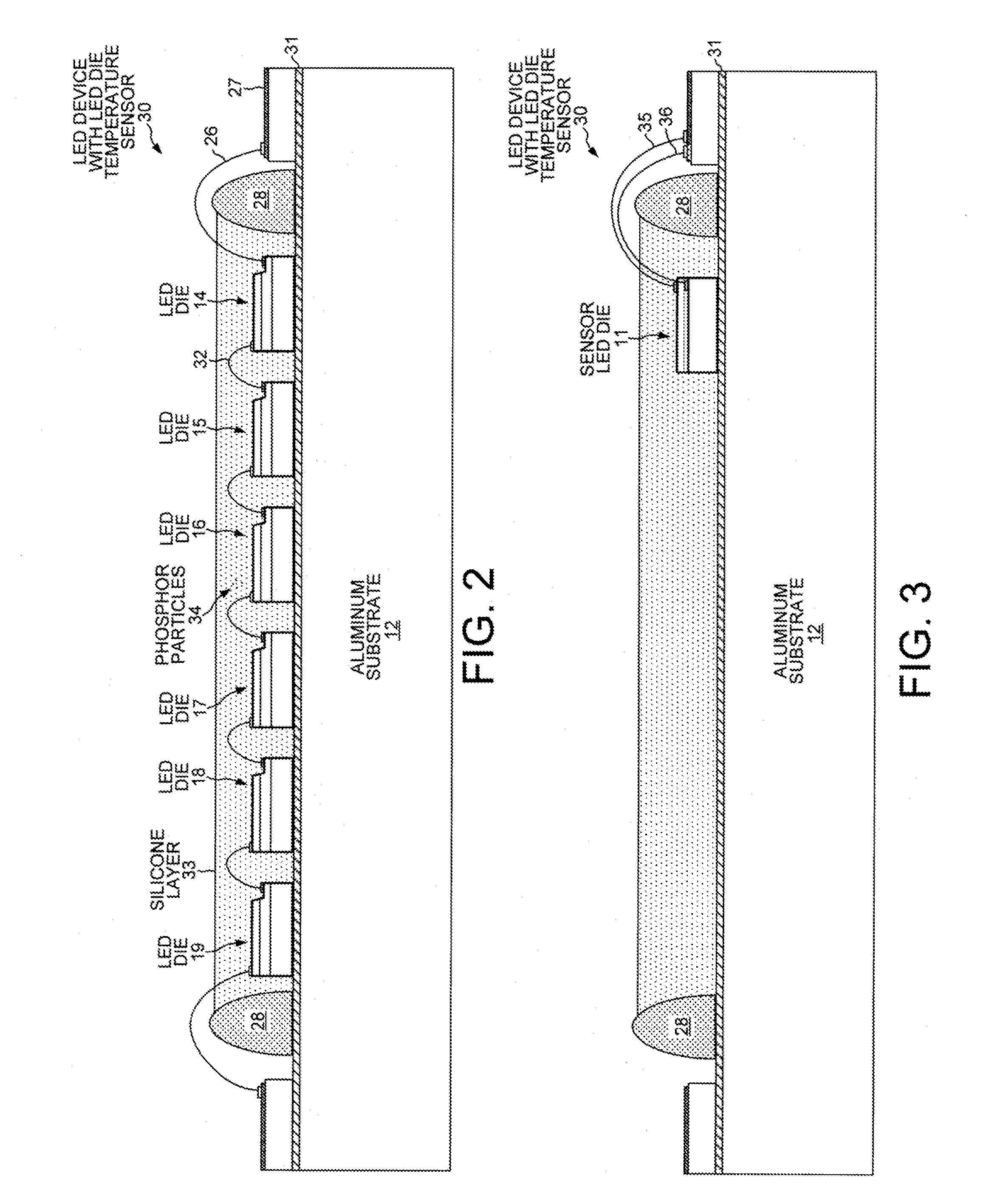
[0020]FIG. 1 shows a light-emitting diode (LED) device 10 with an LED die 11 used to determine the temperature under a transparent carrier material that includes phosphor and that covers an array of other LED dies. LED device 10 includes an array of sixty-one structurally identical LED dies (chips). Each of the LED dies includes epitaxial layers of GaN or GaInN grown on a sapphire substrate. In other embodiments, the gallium-nitride layer is grown on a substrate of crystalline silicon. Each of the sixty-one LED dies is mounted on an aluminum substrate 12 that is housed in a ceramic package 13. The gallium-nitride LED dies emit blue light with a wavelength of about 452 nanometers when a sufficient drive current is passed through the diodes. For example, a string of ten LED dies 14-23 are connected in series such that a drive current can flow ...


PUM


Abstract

A light-emitting diode (LED) device includes first and second LED dies with the same structure and that are both encapsulated by the same silicone layer. The first LED is supplied with sufficient drive current to illuminate the LED. Control circuitry supplies the second LED with a constant current, determines the voltage across the second LED, and calculates the temperature of the second LED based on the voltage across the second LED. The constant current has a maximum magnitude that never exceeds the maximum magnitude of the drive current. The LED device is able to calculate the temperature of a diode with a gallium-nitride layer (GaN or GaInN) that is receiving a large drive current and emitting blue light by determining the voltage across an adjacent similar diode with a gallium-nitride layer through which a small constant current is flowing. Preferably, the band gap of the LEDs exceeds two electron volts.

Description

TECHNICAL FIELD[0001]The present invention relates generally to packaging for light-emitting diodes, and more particularly, to a method of determining the temperature inside a silicone layer that encapsulates an array of LED dies.BACKGROUND INFORMATION[0002]Light emitting diodes (LEDs) are an important class of solid-state devices that convert electric energy into light. Improvements in these devices have resulted in their use as light sources replacing conventional incandescent and fluorescent light fixtures. The energy conversion efficiency of LEDs now approaches the level attained by fluorescent light fixtures and promises to exceed even these efficiencies. Moreover, LEDs have significantly longer lifetimes than both incandescent bulbs and fluorescent tubes. However, the useful lifetime of LEDs is significantly reduced if the operating temperature exceeds certain limits.[0003]The operating environment of an LED light source is typically hot, and overheating must be controlled in ...

Claims


Application Information

Patent Timeline
IPC IPC(8): G01K7/00H05B33/08H05B44/00
CPCG01K7/00H05B33/0842H05B33/0851G01K7/01H01L2224/48091H01L2224/48137H01L2224/49107H01L2224/73265H01L2224/8592H01L2924/181H05B45/18H01L2924/00014H01L2924/00012H01L33/32H01L33/502H01L27/156
Inventor IMANGHOLI, BABAKGERSHOWITZ, MICHAEL NEALWEST, R. SCOTT
Owner SIGNIFY HLDG BV
Why Eureka
Try Eureka