Apparatus and method for measuring electrical properties of matter

Active Publication Date: 2015-01-01
ILIUM TECH
View PDF18 Cites 13 Cited by
  • Summary
  • Abstract
  • Description
  • Claims
  • Application Information

AI Technical Summary

Benefits of technology

[0020]Because of the wide range of values that can be measured by this instrument, it is also desirable to have probes for which the cell constant (defined as A/L, the Area to gap-Length ratio) does not change over the entire range of fluid parameters that might be encountered. The current disclosure also provides a probe design utilizing a fully guarded signal electrode as well

Problems solved by technology

Measuring very low conductivity in liquids (<1 nS/cm) (nano-Siemens per cm) has historically posed a problem for instrumentation.
In addition to the obvious issues with resistive leakage paths, liquids have a tendency to polarize under an electric field and can form double layers at electrode interfaces that can mask the bulk of the sample from the measurement field.
Adding to the measurement problems is that when using an AC measurement waveform, parasitic capacitance shunting the sample being measured can cause large out-of-phase return signals.
This can work well for systems where the out-of-phase return signals are manageable, but as the ratio of out-of-phase to in-phase return components becomes very large, errors tend to increase rapidly, dramatically reducing the accuracy of the measurement.
However, because the out-of-phase return signal, and therefore the compensating subtraction signal, can be orders of magnitude larger than the in-phase return signal of interest, extremely small phase errors in the compensating quadrature phase subtraction signal can cause relatively large measurement accuracy errors.
When using a non-sine wave drive, much of the signal to noise improvement gained by the use of narrow band drive signals can be lost.
This can limit the frequencies that c

Method used


Image

  • Apparatus and method for measuring electrical properties of matter
  • Apparatus and method for measuring electrical properties of matter
  • Apparatus and method for measuring electrical properties of matter

Examples


Embodiment Construction

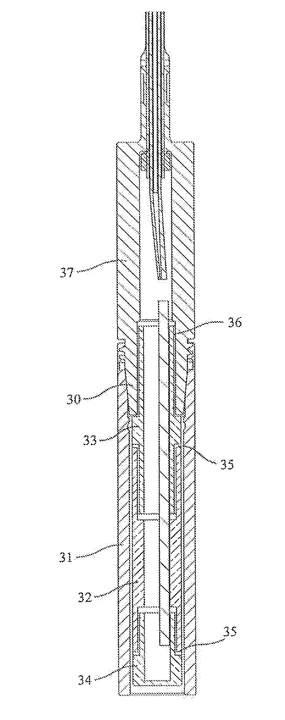
[0027]The present disclosure provides a method for measuring the electrical conductivity, dielectric constant, and related properties of liquids and an apparatus that implements said method. The present disclosure also provides a guarded probe for use with the measurement apparatus.

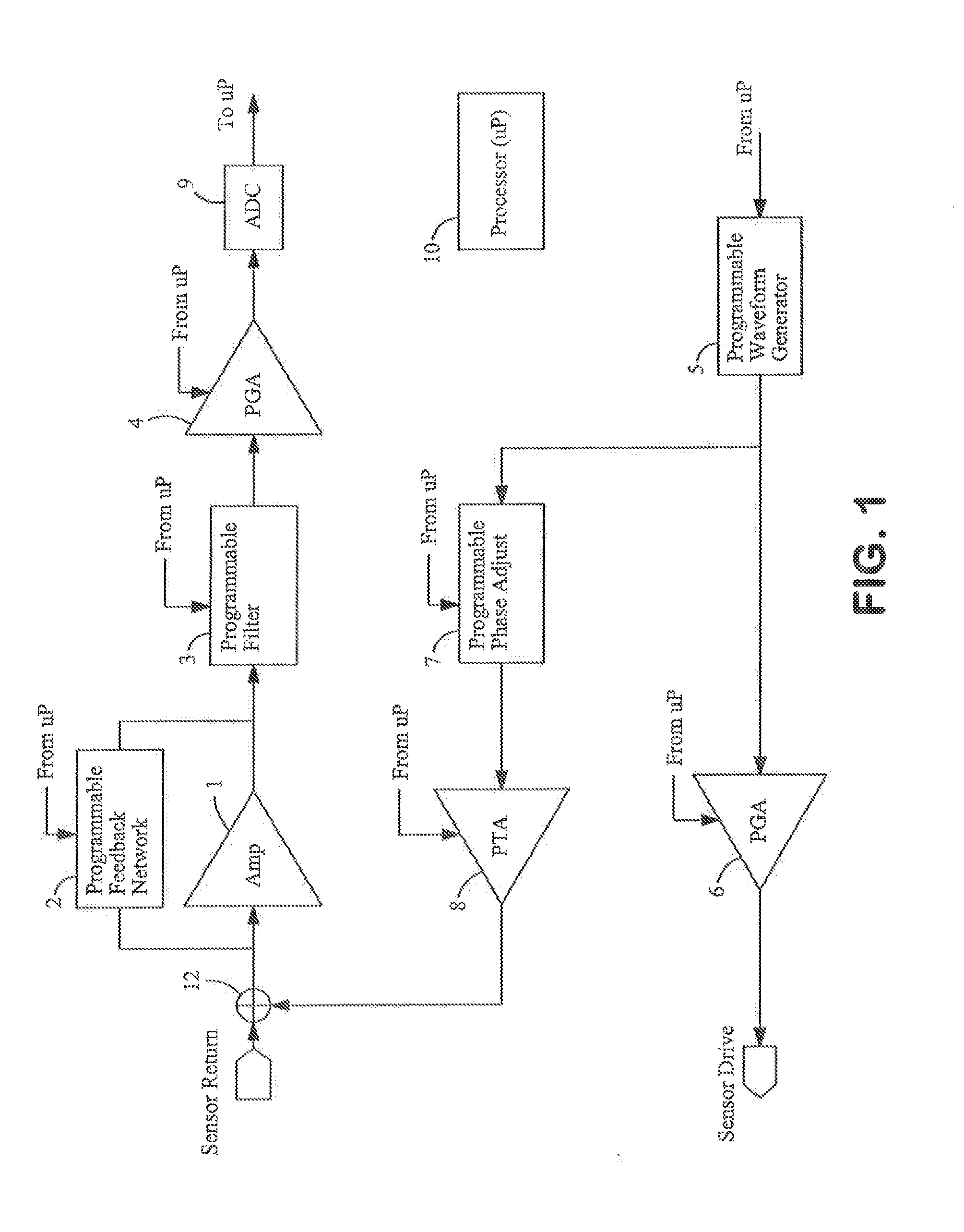
[0028]FIG. 1 shows a schematic circuit diagram according to an embodiment of the present disclosure, the circuit comprising major components indicated below as being coupled to a liquid sample sensor (cell or probe) and to a processor. The processor 10 can be of standard form, e.g., a Texas Instruments TMS320F2808 microprocessor controller for transmitting manual and / or programmed instructions to the circuit components and storing and managing data obtained. It is programmed to implement the process steps described below.

[0029]The return-signal-processing-unit's amplifiers and filters whose characteristics can be dynamically changed are schematically represented by amplifier 1, feedback network 2, program...


PUM


Abstract

The present disclosure provides a method and an apparatus for measuring electrical conductivity of liquids. In one aspect, the apparatus includes a waveform generator module configured to generate a first waveform signal and to supply the first waveform signal to a sensor; a phase adjustment module configured to receive the first waveform signal from the waveform generator module and to generate a phase-shifted signal from the first waveform signal, said phase-shifted signal having a phase that is adjusted based upon expected or measured properties of the liquid and further adjusted to eliminate phase error induced inaccuracies in the measurement; and a signal combination module configured to receive a return signal from the sensor and the phase-shifted signal from the phase adjustment module and to sum the return signal and the phase-shifted signal to produce an adjusted return signal containing information associated with the electrical property of the liquid.

Description

RELATED APPLICATION[0001]This application claims priority to U.S. Provisional Application No. 61 / 790,668, filed on Mar. 15, 2013, the entire contents of which are incorporated herein by reference, for all purposes, as if stated / shown at length herein.TECHNICAL FIELD[0002]The present disclosure relates to an apparatus and a method for measuring the electrical conductivity, dielectric constant, and related properties of matter and includes apparatus and a method for precisely measuring the electrical conductivity of liquids with conductivities ranging from extremely low (˜10−15 S / cm) to moderately high (˜10−3 S / cm). (S / cm=Siemens per centimeter).RELATED ART[0003]Measuring very low conductivity in liquids (<1 nS / cm) (nano-Siemens per cm) has historically posed a problem for instrumentation. In addition to the obvious issues with resistive leakage paths, liquids have a tendency to polarize under an electric field and can form double layers at electrode interfaces that can mask the bu...

Claims


Application Information

Patent Timeline
IPC IPC(8): G01N27/02
CPCG01N27/02G01N27/028G01N27/06G01N27/07
Inventor HERB, GLENN T.HERB, CRAIG A.JARVA, CURT W.
Owner ILIUM TECH
Why Eureka
Try Eureka