Acid gas management in liquid fuel production process

a technology of liquid fuel production and acid gas management, applied in the direction of combustible gas purification/modification, combustible gas production, oxygen-containing compound preparation, etc., to facilitate the formation of gasifier syngas and facilitate the formation of h2-rich syngas

Active Publication Date: 2015-01-01
PRAXAIR TECH INC
View PDF3 Cites 38 Cited by
  • Summary
  • Abstract
  • Description
  • Claims
  • Application Information

AI Technical Summary

Benefits of technology

[0017]According to an aspect of the invention, a method and system is provided for producing liquid fuel product from solid feedstock materials and light fossil fuels for converting a solid carbonaceous material (10) in a gasification unit (2) to form a gasifier syngas (24); passing the gasifier syngas (24) to a gas conditioning unit (4), and treating the gasifier syngas (24) therein forming: at least a treated gasifier syngas stream (26) containing at least 50% of CO2 in the gasifier syngas (24), a CO2-enriched gas stream (7A), and a sulfur-enriched stream (500); utilizing at least a portion of the CO2-enriched gas stream (7A) containing at least 90% of CO2 removed from the gasifier syngas in the formation of gasifier syngas (24). It also provides for converting a light fossil fuel (18) in a light fossil fuel conversion unit (6) to form a H2-rich syngas (27) comprising H2 and CO at a H2 / CO mole ratio of at least 2:1; combining treated gasifier syngas (26) and H2-rich syngas (27) to form a mixed syngas (30) having a H2 / CO ratio greater than that of treated gasifier syngas stream (26); converting the mixed syngas (30) to form at least a liquid fuel product (32) and a byproduct stream (34) comprising one or more of hydrogen, CO, water vapor, methane, and hydrocarbons containing 2 to 8 carbon atoms and 0 to 2 oxygen atoms. Furthermore it provides for reacting up to 100% of the byproduct stream (34) in the light fossil fuel conversion unit (6) to facilitate formation of the H2-rich syngas (27); and utilizing the CO2-enriched gas stream (7D) to facilitate formation of the gasifier syngas (24).

Problems solved by technology

However, IGCC systems primarily focus on making electricity and to a limited extent on liquid fuels production.

Method used


Image

  • Acid gas management in liquid fuel production process
  • Acid gas management in liquid fuel production process
  • Acid gas management in liquid fuel production process

Examples


case 1

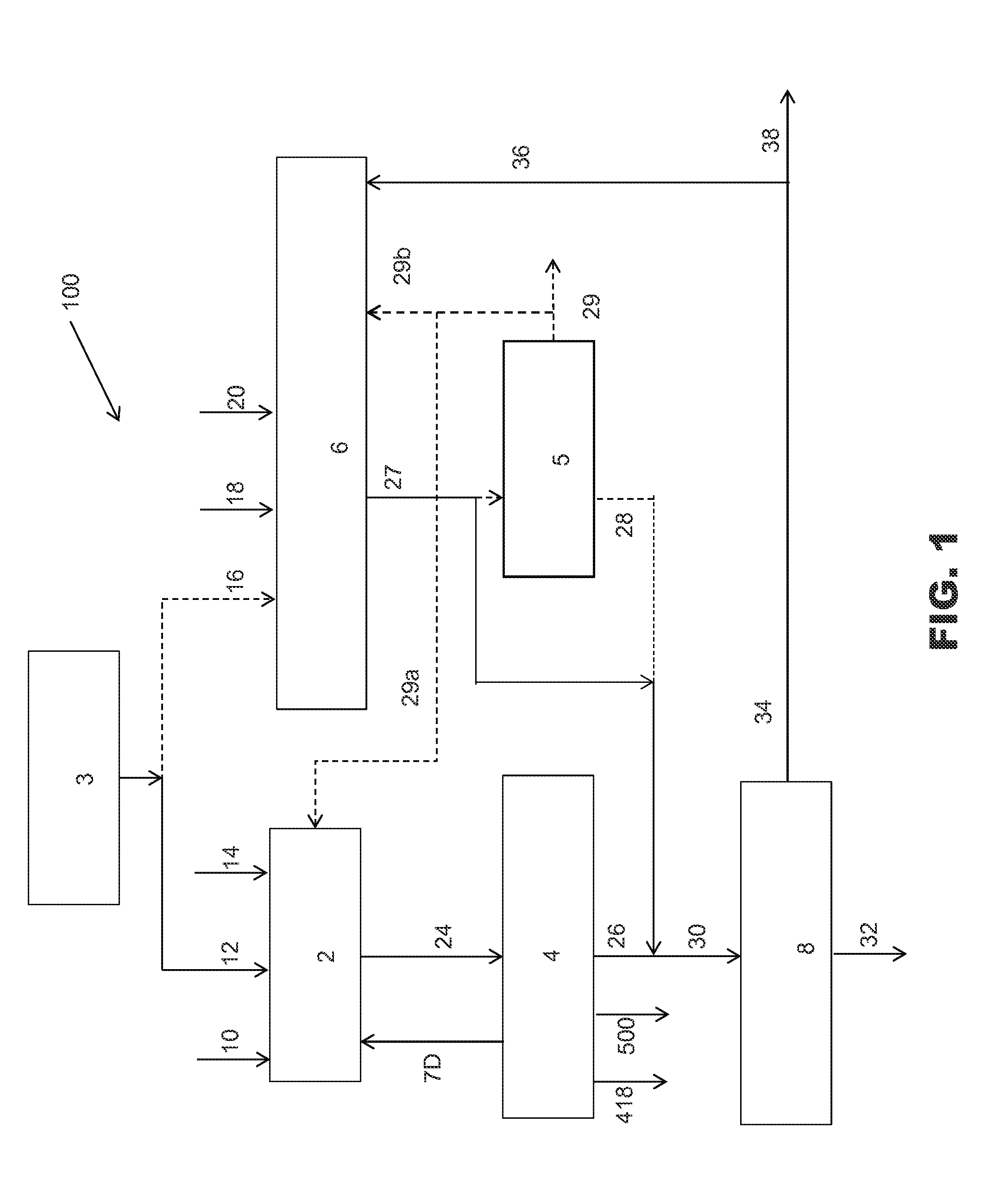
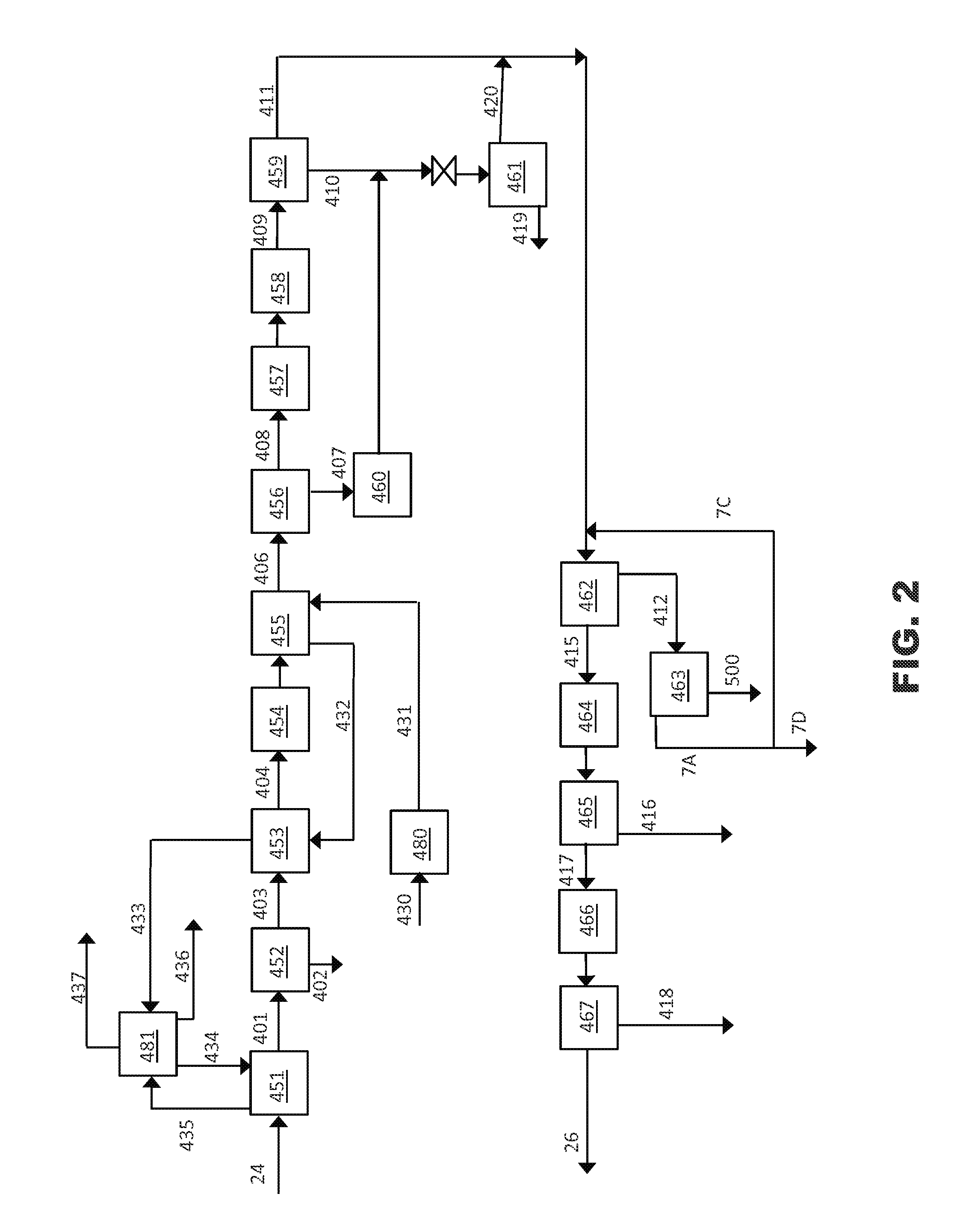
[0089]This is the base case where CO2 content in the bio-syngas, stream 24 is reduced from 26 vol. % to 1.5 vol. % in stream 26. 90% of the byproduct gas from the liquid fuel production unit is fed as a reactant to the SMR.

case 2 (

[0090This invention)—CO2 content in the gasifier syngas 24 is reduced from 26 vol. % to 18.6 vol. % in stream 26. CO2 removed is returned to the gasifier. 63% of the byproduct gas from the liquid fuel production unit is fed as a reactant to the SMR.

Case 1Case 2Gasifier syngas 24, MMSCFD45.245.2Treated gasifier syngas 26Flow, MMSCFD33.941.1H2 / CO ratio0.870.87CO2, mol %1.5%18.6%Unit 4CO2 rejected in unit 4, tons / day650230% of CO2 in gasifier syngas removed by unit 495.6%34.1%Calculated steam consumption, MMBtu / day1950690CO2-rich stream 7D to gasifier, MMSCFD44CO2 to vent, tons / day4180Acid gas rich stream to sulfur recovery system in11.34.1unit 4, MMSCFDByproduct stream 36, fraction as feed0.90.63Natural gas 18 split, fraction as feed0.490.77H2-rich Syngas (27) H2 / CO ratio33H2-rich Syngas (27) CO2 vol. %16.4%16.8%H2-rich Syngas (27) flow, MMscfd76.976.5Mixed Syngas (30) H2 / CO ratio1.91.9Mixed Syngas (30) CO2 vol. %11.8%17.5%Mixed Syngas (30) flow, MMscfd111118Biomass (10), tpd (dry)900...


PUM

PropertyMeasurementUnit
temperatureaaaaaaaaaa

Abstract

A process and method for producing liquid fuel product from hydrogen and carbon monoxide containing streams produced by gasifying solid carbonaceous feedstock and steam reforming of light fossil fuels. The gasifier syngas is treated to preferentially remove at least 99% of sulfur containing impurities and less than 50% of the CO2 to produce a treated gasifier syngas and a CO2 enriched gas. The treated gasifier syngas and the light fossil fuel conversion unit product gas are combined to form a mixed syngas that is converted into a liquid fuel product. The CO2 enriched gas is used in the gasification unit.

Description

BACKGROUND OF THE INVENTION[0001]1. Field of the Invention[0002]The present invention relates to acid gas management schemes in the production of liquid fuels from hydrogen and carbon monoxide containing streams using light fossil fuel (for e.g. methane, natural gas, liquefied petroleum gas, naphtha), and solid feedstock such as biomass, coal, petroleum coke and the like.[0003]2. Description of Related Art[0004]Liquid fuels can be produced from solid feedstock materials by first gasifying the solid feedstock material to form hydrogen and carbon monoxide containing stream (gasifier syngas) that is further treated to form desired liquid fuel product.[0005]Gasification of feedstocks such as coal or petroleum coke in an entrained flow gasifier generates a syngas with H2 / CO ratio in the range of 0.4:1 to 0.8:1. CO2 content of the syngas is typically <10 vol. %. Gasification of feedstocks such as biomass in a fluidized bed gasifier typically generates a syngas with H2 / CO ratio in the r...

Claims


Application Information

Patent Timeline
Patent Type & Authority Applications(United States)
IPC IPC(8): C10G2/00C10K1/00
CPCC10G2/30C10K1/004C01B3/24C01B3/38C10J3/00C10J2300/0916C10J2300/093C10J2300/0943C10J2300/0959C10J2300/0969C10J2300/0976C10J2300/1659C10J2300/1678C10K1/005C10K3/06C01B2203/0233C01B2203/0244C01B2203/062C01B2203/0816C01B2203/1241C01B2203/141C01B2203/142Y02E20/18Y02P20/145
Inventor CHAKRAVARTI, SHRIKARDRNEVICH, RAYMOND F.SHAH, MINISH M.
Owner PRAXAIR TECH INC
Why Eureka
Try Eureka