Angular multiplexed optical projection tomography

a tomography and optical projection technology, applied in the field of three-dimensional imaging systems, can solve the problems of difficult to achieve the effect of reducing the working distance, less suitable for larger samples, and reducing the accuracy of the image,

Inactive Publication Date: 2015-01-08
IMPERIAL INNOVATIONS LTD
View PDF6 Cites 8 Cited by
  • Summary
  • Abstract
  • Description
  • Claims
  • Application Information

AI Technical Summary

Benefits of technology

[0029]Some embodiments of the invention may permit the use of multiple simultaneous imaging directions by arranging for the sample to be rotated in a chamber where the imaging lenses (objective lenses) are integrated into the walls of the chamber.
[003

Problems solved by technology

Thus, while they are widely used to image microscopic specimens, they are less suitable for larger samples for which the acquisition of 3-D data sets can be very time consuming.
This is appropriate for X-ray CT, but optical scattering can be a significant issue when imaging in biological tissue.
This is important because mechanical “sectioning” can damage fragile samples.
Tw

Method used


Image

  • Angular multiplexed optical projection tomography
  • Angular multiplexed optical projection tomography
  • Angular multiplexed optical projection tomography

Examples


Embodiment Construction

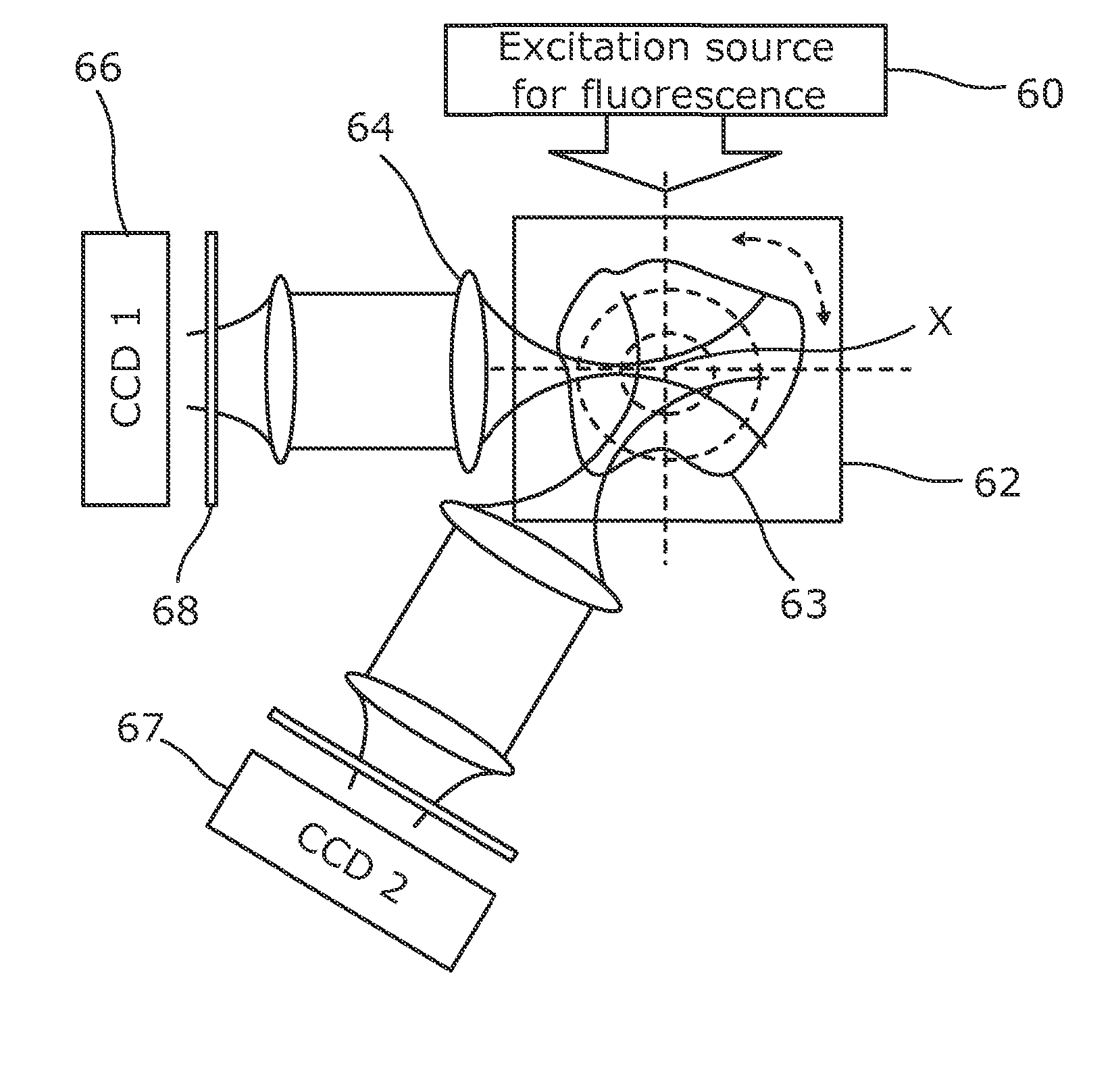
[0048]Referring to FIG. 6 an imaging system according to an embodiment of the invention comprises a single light source 60 and a sample chamber 62 having a rotatable sample holder for supporting a sample 63 and arranged to rotate the sample about an axis of rotation X. Two detector arrays 66, 67 are each arranged to detect fluorescent emissions from the sample 63 and are offset from the transmission direction of the source 60 by different amounts, in this case 45° and 90°.

[0049]Each of the detector arrays 66, 67 has its own optical system, in each case comprising lenses 64 and a filter 68. In this embodiment each of the CCD arrays 66, 67 faces in the direction from which light will be emitted from the sample 63 to reach the it, so the two detector arrays are arranged to generate image data for projection angles that are separated by 45°. This angular separation can be selected as desired by altering the position of one of the CCD arrays with its optical system, or by modifying one o...


PUM


Abstract

An optical projection tomography system comprises a support arranged to support an object (63) and to rotate the object between a plurality of orientations, a first imaging system (64) arranged to image the object from a first direction to form a first image, and a second imaging system arranged to image the object from a second direction to form a second image, data acquisition means (66, 67) arranged to acquire image data from the first and second images for each of the orientations and processing means arranged to process the image data to generate an image data set.

Description

FIELD OF THE INVENTION [0001]The present invention relates to three-dimensional imaging systems, and in particular to optical projection tomography systems, for example for imaging mesoscopic biological samples.BACKGROUND TO THE INVENTION[0002]As biological research progresses from studies of mono-layers of cells on glass to in situ measurements of both ex vivo and in vivo biological systems, it becomes necessary to apply three-dimensional (3-D) imaging techniques in order to map structure and function throughout a sample. Confocal / multiphoton / harmonic generation laser scanning microscopes provide optical sectioning to permit the acquisition of 3-D z-stacks (stacks of planar images) and also offer improved contrast compared to wide-field imaging but they suffer from limited (100's μm) penetration depth and fields of view (10's μm) and exhibit anisotropic resolution. Thus, while they are widely used to image microscopic specimens, they are less suitable for larger samples for which t...

Claims


Application Information

Patent Timeline
IPC IPC(8): G01N21/64G01N21/47
CPCG01N21/6486G01N21/47G01N2201/0697G01N2201/08G01N2201/06113G01N21/4795G01N21/6408G01N21/6456
Inventor FRENCH, PAUL MICHAEL WILLIAMMCGINTY, JAMES ANDREW
Owner IMPERIAL INNOVATIONS LTD
Why Eureka
Try Eureka