Heat transfer control in pecvd systems

Inactive Publication Date: 2015-01-08
OERLIKON SOLAR AG (TRUEBBACH)
View PDF2 Cites 2 Cited by
  • Summary
  • Abstract
  • Description
  • Claims
  • Application Information

AI Technical Summary

Benefits of technology

The patent describes a method for manufacturing thin films on substrates using a deposition system. The system includes an inner non-airtight enclosure for containing the substrate and an outer airtight chamber. The inner enclosure is maintained at a lower pressure than the outer chamber, and a backfilling gas is introduced into the outer chamber to prevent contamination of the process environment. The pressure difference between the inner and outer chambers is less than 1 mbar. The system also includes cooling plates that improve heat transfer and allow for easy replacement of the enclosures. The method reduces contamination, improves heat transfer, and reduces the vacuum pumping requirement. The thin films produced using this method include silicon films, which are commonly used in semiconductor device production.

Problems solved by technology

The power however results in a considerable heat-up of the reactor and the substrate involved.
Temperatures of more than 200° C. however are often detrimental for the material and electrical properties of the layers already deposited.
However, even though the pressure in volume 75 was controlled to be lower than the pressure in reactors 70-72, the purge gas cannot completely be prevented from entering inner reactors 70-72.
This has turned out to be a problem since even traces of nitrogen incorporated in the absorber layer of a photovoltaic stack, i.e. the intrinsic silicon layer, deteriorate the properties of the photovoltaic element, especially in case of microcrystalline silicon.
The obvious solution to replace nitrogen by another inert gas like argon is too costly.
Increasing deposition rates in a system as described above always requires increasing the RF power fed to the reactors, which inevitably increases the need to reduce excessive heating of the equipment and the substrates treated.
Insufficient cooling will thus lead to a heating-up of the substrate over the time of deposition and will therefore affect the layer properties.
This however has new disadvantages: Besides the fact, that any increase of pumping power is costly, the leak rate from the reactors to the outer chamber would increase (loss of working gases) which results in contamination of the outer chamber 76.
Further, the leak flow is not homogeneous over the sealing area, in other words, depending on the chamber geometry, contamination, mechanical tolerances, certain areas will leak more than others.
This leak flow pattern affects the layer homogeneity locally; it will likely copy such inhomogeneity as a flow pattern on the substrate, which will finally negatively affect the quality of the substrates treated.
However, in order to reduce the leakage to the outer chamber, the inner reactors should be sealed; however, seals capable of handling operation temperatures of up to 200° C. or up to 250° C. and having sufficient fluorine resistance are expensive.

Method used


Image

  • Heat transfer control in pecvd systems
  • Heat transfer control in pecvd systems

Examples


Embodiment Construction

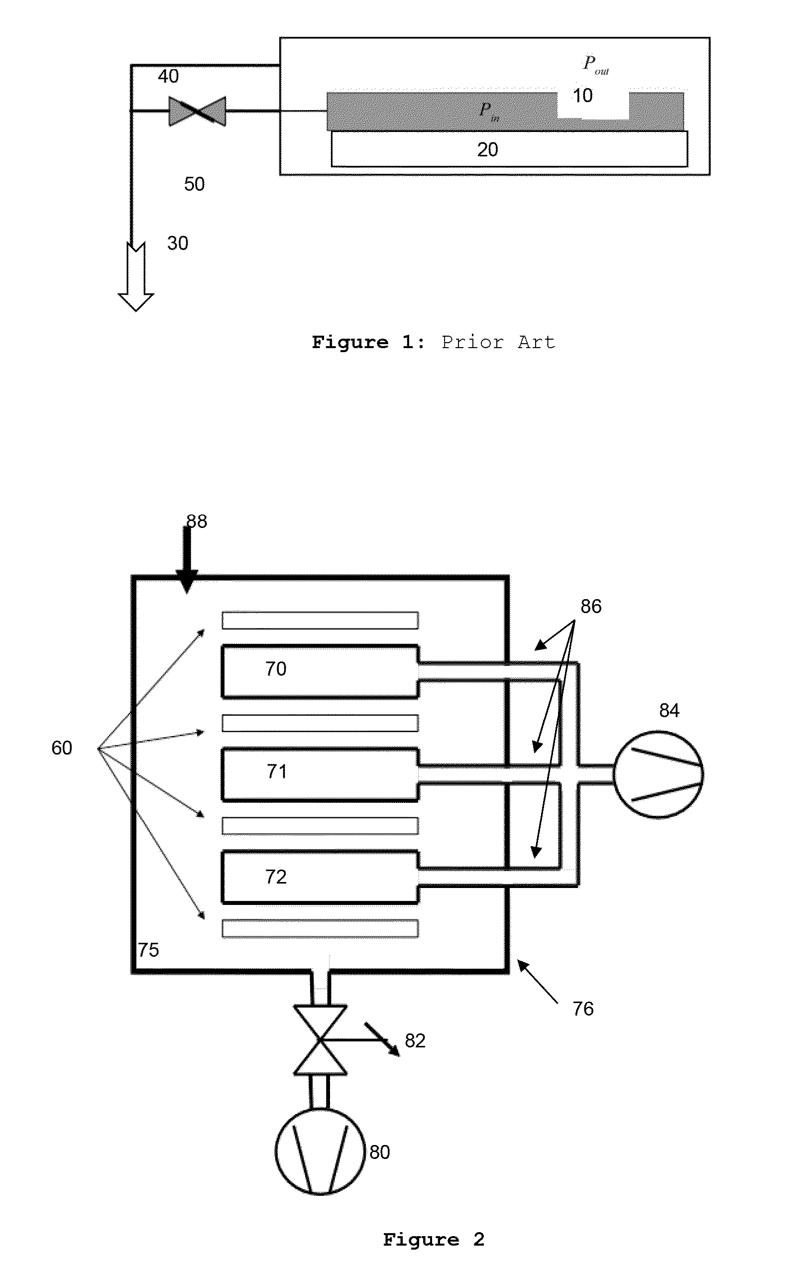
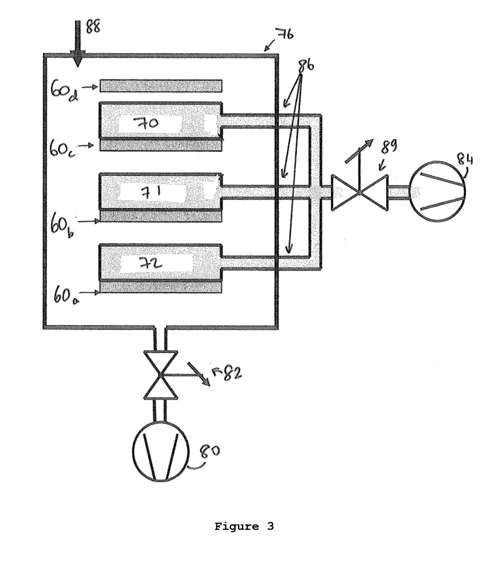
[0032]According to the invention, the deposition process shall be modified as follows: During a deposition cycle H2 gas is fed via inlet 88 into chamber 76 to increase the pressure in volume 75. The pressure can be controlled by the H2 gas inflow and / or a control valve 82 in the pump line. Up to about 10 mbar pressure the heat conductance increases with increasing gas pressure, so for high RF power applied in reactors 70-72 such a high pressure regime is preferred. It is further proposed to arrange cooling plates 60 very close to the reactor, preferable having a distance in the range of less than 3 mm, preferably less than 1 mm. This close arrangement allows better heat transfer from the reactors 70-72 to cooling plates 60. By not fixedly mounting cooling plates 60 to reactors 70-72 it is still possible to quickly remove the reactors from a stack as shown in FIG. 2. Typically, the distance between the reactor bottom and the adjacent cooling plate is 15-20 mm.

[0033]As has been outlin...


PUM

PropertyMeasurementUnit
Temperatureaaaaaaaaaa
Pressureaaaaaaaaaa

Abstract

The invention relates to a method for manufacturing thin films on substrates, the method comprising providing a deposition system, said system comprising an inner non-airtight enclosure for containing at least one substrate and an outer airtight chamber completely surrounding said enclosure, and providing at least one substrate in the inner non-airtight enclosure. The inner non-airtight enclosure is maintained at a pressure lower than the pressure within said outer airtight chamber, and a backfilling gas comprising at least hydrogen or helium is introduced into the outer airtight chamber volume.

Description

CROSS REFERENCE TO RELATED APPLICATIONS[0001]This application is a 35 U.S.C. 371 National Phase Entry Application from PCT / EP2012 / 076434, filed Dec. 20, 2012, which claims the benefit of U.S. Provisional Application No. 61 / 582,871, filed Jan. 4, 2012, the disclosures of which are incorporated herein in their entirety by reference.[0002]This invention relates to improvements in systems for depositing of thin films, especially thin silicon films with low contamination, by means of plasma enhanced chemical vapor deposition (PECVD). In more detail it refers to improvements of a deposition process used in a parallel-plate reactor known in the art.DEFINITIONS[0003]Substrates in the sense of this invention are components, parts or work pieces to be treated in a processing apparatus. Substrates include but are not limited to flat, plate shaped parts having rectangular, square or circular shape.[0004]CVD Chemical Vapour Deposition is a well-known technology allowing the deposition of layers ...

Claims


Application Information

Patent Timeline
IPC IPC(8): C23C16/44C23C16/513
CPCC23C16/4411C23C16/513C23C16/44C23C16/4401C23C16/45557C23C16/463C23C16/466
Inventor JOST, STEPHANCHAUDHARY, DEVENDRAKLINDWORTH, MARKUS
Owner OERLIKON SOLAR AG (TRUEBBACH)
Why Eureka
Try Eureka