Electromagnetic valve

Active Publication Date: 2015-01-29
DENSO CORP
View PDF4 Cites 21 Cited by
  • Summary
  • Abstract
  • Description
  • Claims
  • Application Information

AI Technical Summary

Benefits of technology

[0026]According to an aspect of the disclosure, the first stepped portion on the shaft and the second stepped portion on the movable core are engaged by the male-female joint. Therefore, it is possible to reduce lateral offset of the shaft to the movable core and an inclination of the shaft to the movable core. Even if the finishing of the cup guide is the same as the comparative embodiment 1, it is possible to reduce slanting load generated on the spool or the shaft due to an inclination of the shaft with respect to the central axis of the spool. It is possible to reduce side forces. It is possible to reduce sticking of the plunger. As a result, it is possible to improve control ability of the movable components including the plunger, the shaft and the spool with res

Problems solved by technology

Therefore, it is impossible to open the chambers to the air, since it is necessary to prevent oil from leaking outside of the engine.
However, this OCV may suck foreign matters with oil through the sub-drain port.
In a case that if a foreign matter enters into the slide clearance, the cup guide or the plunger may not slide smooth or may create an unexpected amount of abrasion.
However, in the case of OCV in Patent Lit

Method used


Image

  • Electromagnetic valve
  • Electromagnetic valve
  • Electromagnetic valve

Examples


first embodiment

[0047]Hereafter, the form of implementation of the present invention is explained in detail based on a drawing.

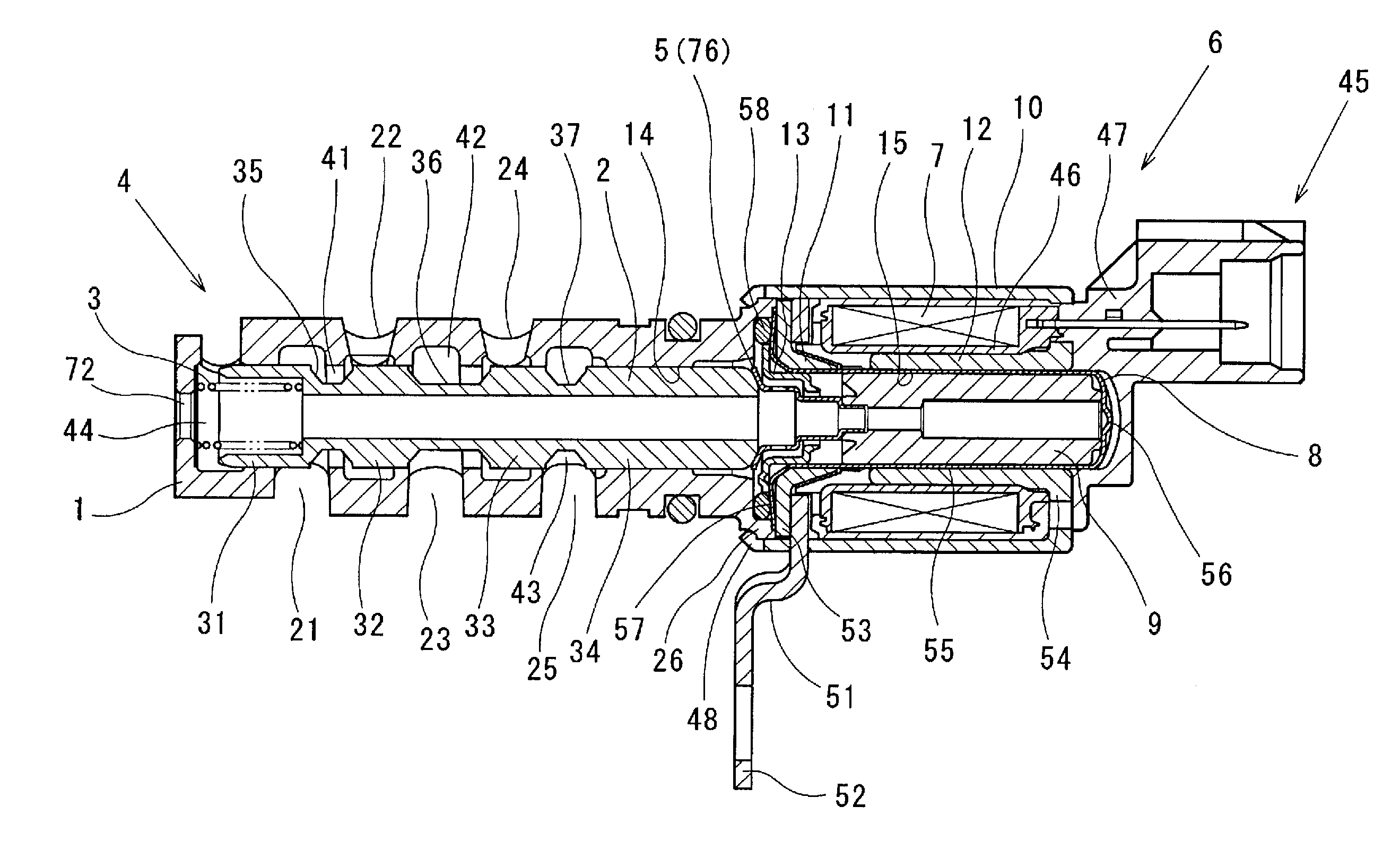
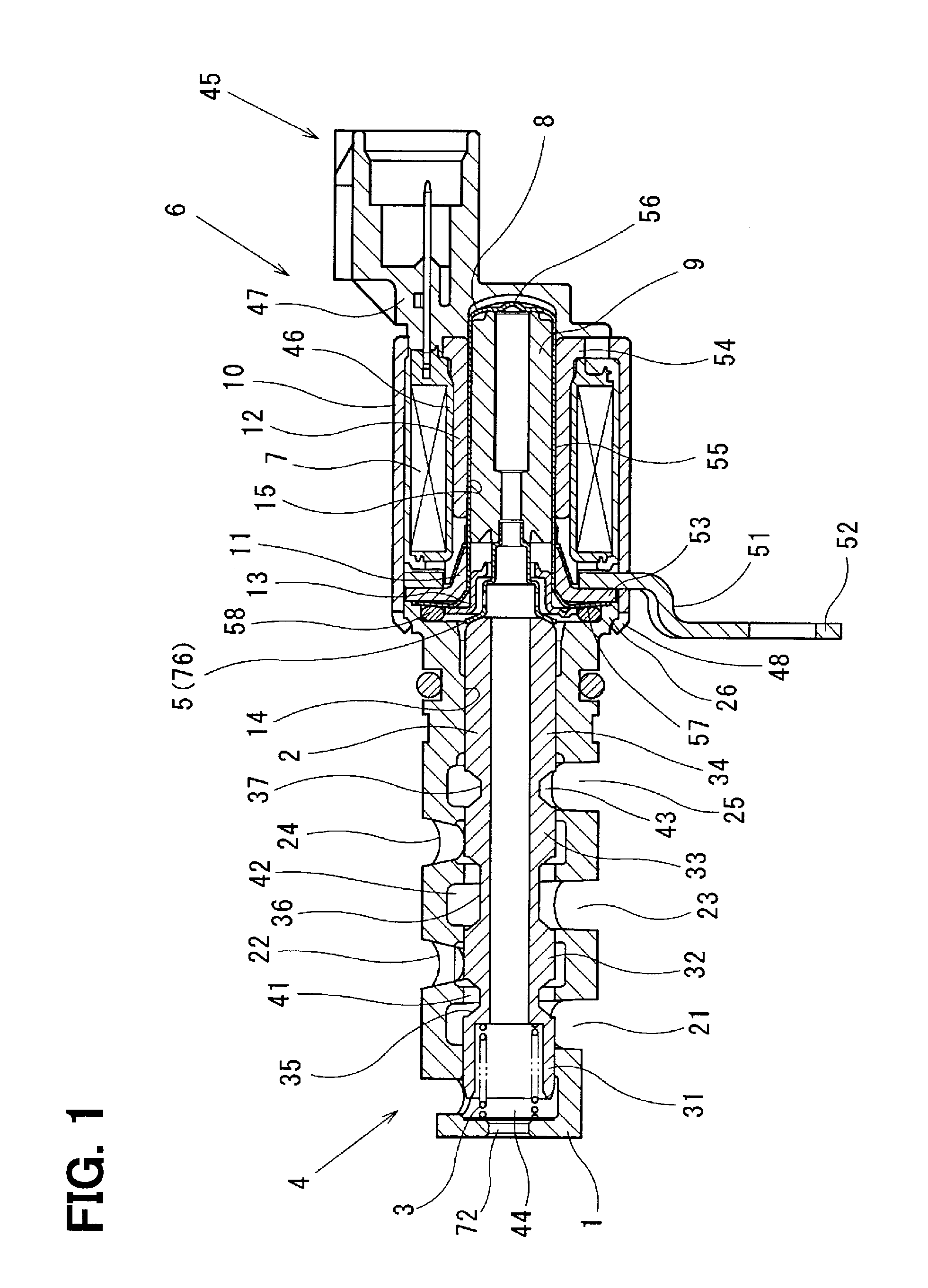
[0048]FIGS. 1 to 4 show an electromagnetic oil control valve (OCV) which is used as a component of a variable valve timing system for an internal combustion engine (ICE). OCV is operated to control oil flow supplied to and discharged from a variable valve timing mechanism (VVT).

[0049]The variable valve timing system includes VVT, an oil circuit, OCV, and an engine control unit (ECU). VVT may vary an opening timing and / or a closing timing of a valve of ICE in a continuously variable manner. The valve may be an intake valve, an exhaust valve or both of them. VVT may be disposed on a drive train for a camshaft for operating the valve. ICE may be mounted on a vehicle to move the vehicle. The oil circuit is arranged to control VVT. The oil circuit is arranged to supply oil to VVT and retrieve oil from VVT. OCV is installed in the oil circuit. ECU electrically controls OCV.

[0050]...

second embodiment

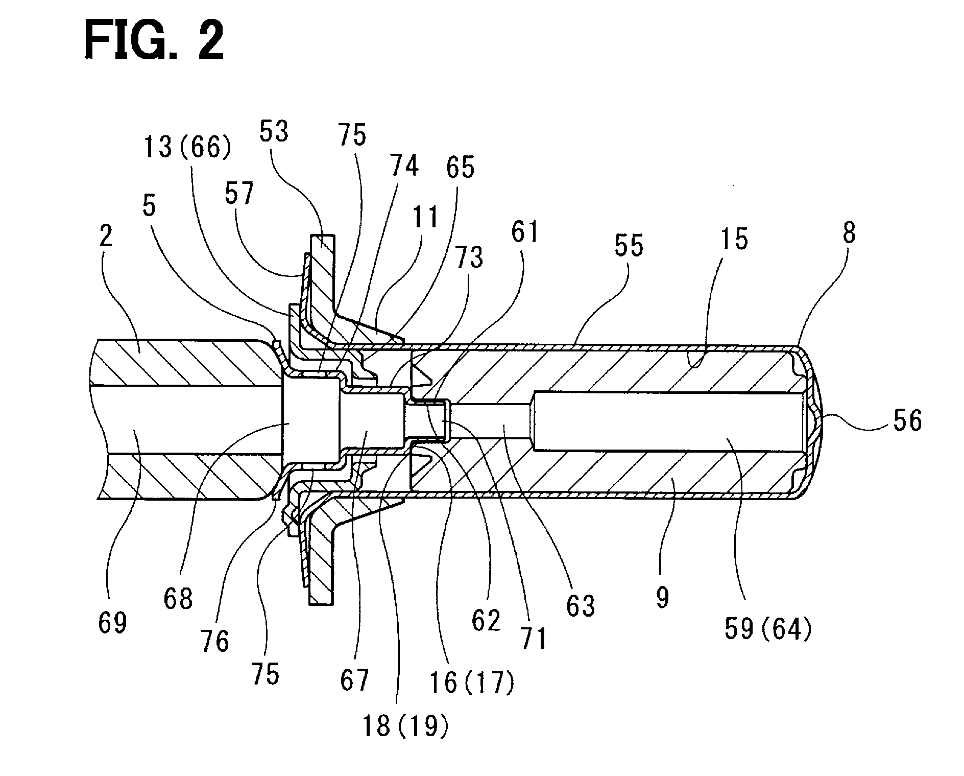
[0122]FIG. 5A shows OCV of a second embodiment. The same reference symbols as in the first and second embodiments are used to show the same or equivalent components of which descriptions can be found above.

[0123]The projection 61 on the cup shaft 5 has a tapered profile. The tapered profile on the projection 61 provides two or more force transmitting points from the plunger 9 to the cup shaft 5. The force transmitting points are apart from each other and located on both sides of the central axis CL of the spool 2. The projection 61 is formed to have a tapered profile defining gradually decreasing outer diameter from a base to a distal end of the projection 61. The recess 62 is formed to have a tapered inner profile which corresponds to the tapered profile of the projection 61. The recess 62 may be formed to have a slightly larger inner diameter than the outer diameter of the projection 61, when the cup shaft 5 rests on the plunger 9. As mentioned above, this OCV has similar advantag...

third embodiment

[0124]FIG. 5B shows OCV of a third embodiment. The same reference symbols as in the first and second embodiments are used to show the same or equivalent components of which descriptions can be found above.

[0125]The projection 61 on the cup shaft 5 has a curved profile. The curved profile on the projection 61 provides two or more force transmitting points from the plunger 9 to the cup shaft 5. The force transmitting points are apart from each other and located on both sides of the central axis CL of the spool 2. The curved profile is provided by a spherical profile which has a predetermined radius having a center on a point located on the central axis of the cup shaft 5. The recess 62 on the plunger 9 presents the same profile as described in the first embodiment. As mentioned above, this OCV has similar advantages as described in the preceding embodiments.

Other Embodiments

[0126]In the illustrated embodiments, the electromagnetic valve according to the present disclosure is applied t...


PUM


Abstract

An oil control valve has a cup shaft and a plunger. The cup shaft and the plunger have a projection and a recess to provide a male-female joint. The male-female joint provides contact points which can reduce lateral offset and inclination. The projection and The recess provides two or more force transmitting points from the plunger to the cup shaft, when the projection and the recess are inclined with each other. The force transmitting points are located about the central axis of the spool in a distributed manner.

Description

CROSS REFERENCE TO RELATED APPLICATION[0001]This application is based on Japanese Patent Application No. 2013-153336 filed on Jul. 24, 2013, the disclosure of which is incorporated herein by reference.TECHNICAL FIELD[0002]The present disclosure relates to an electromagnetic valve.BACKGROUND[0003]Patent Literature 1: JP4618133B[0004]Patent Literature 2: JP4665869B[0005]Patent Literatures 1 and 2 disclose electromagnetic oil control valves (hereinafter referred to as OCV) for a pressurized oil circuit for a variable valve timing mechanism (hereinafter referred to as VVT) for an internal combustion engine (hereinafter referred to as ICE.) OCV is operated to control oil supply to and oil discharge from an advancing chamber and a retarding chamber which are disposed in an actuator for VVT.[0006]OCV is an electromagnetic valve that has a spool valve and an electromagnetic actuator which are axially connected on an axial direction. The spool valve has a cylindrical sleeve and a spool suppo...

Claims


Application Information

Patent Timeline
IPC IPC(8): F15B13/04F01L1/34F16K31/06
CPCF15B13/0402F15B2013/0412F01L1/34F16K31/0613F16K27/029F01L2001/3443F01L2820/01F01L2810/02Y10T137/86622Y10T137/8671Y10T137/8667Y10T137/86702F16K27/048F16K31/0603F16K31/048F16K31/04F16K31/0675
Inventor OCHIAI, MASAHIKOKONDO, JIRO
Owner DENSO CORP
Why Eureka
Try Eureka