Mechanical structure component, sintered gear, and methods of manufacturing mechanical structure component and sintered gear

a technology of mechanical structure and gear, which is applied in the direction of mechanical equipment, transportation and packaging, mechanical structures, etc., can solve the problems of increasing material loss, increasing material loss, and reducing the strength of mechanical structure components such as gears made of sintered bodies, so as to suppress the decrease in dimensional accuracy, improve static strength, toughness and fatigue strength

Inactive Publication Date: 2015-02-05
NTN CORP
View PDF0 Cites 4 Cited by
  • Summary
  • Abstract
  • Description
  • Claims
  • Application Information

AI Technical Summary

Benefits of technology

[0041]As apparent from the above description, according to the mechanical structure component and the method of manufacturing the same in accordance with the present invention, it becomes possible to provide a mechanical structure component allowing improvement in static strength, toughness and fatigue strength while suppressing a decrease in dimensional accuracy, and a method of manufacturing the mechanical structure component. Furthermore, according to the sintered gear and the method of manufacturing the same in accordance with the present invention, it becomes possible to provide a sintered gear having high shape accuracy and capable of exhibiting high fatigue characteristics, and a method of manufacturing the sintered gear.

Problems solved by technology

Accordingly, the cutting process tends to require a relatively long time or powder scrap tends to occur to increase loss of materials.
Accordingly, the mechanical structure component such as a gear made of a sintered body tends to be inferior in static strength, toughness and fatigue strength than the component made of a melting material even if both are made of materials of equal quality.
Consequently, the application of the mechanical structure component made of a sintered body has been limited.
According to the methods described above, however, although static strength, toughness and fatigue strength can be improved, there occurs a problem that shape deformation occurs due to release of residual stress and the like by adding thermal history, thereby decreasing the dimensional accuracy.
In particular, the sinter-forging method causes a problem that the dimensional accuracy is further decreased by carrying out hot forging.
Furthermore, since the methods disclosed in the above-described PTD 1 and PTD 2 each include special processes, the manufacturing cost also tends to increase.

Method used


Image

  • Mechanical structure component, sintered gear, and methods of manufacturing mechanical structure component and sintered gear
  • Mechanical structure component, sintered gear, and methods of manufacturing mechanical structure component and sintered gear
  • Mechanical structure component, sintered gear, and methods of manufacturing mechanical structure component and sintered gear

Examples


examples

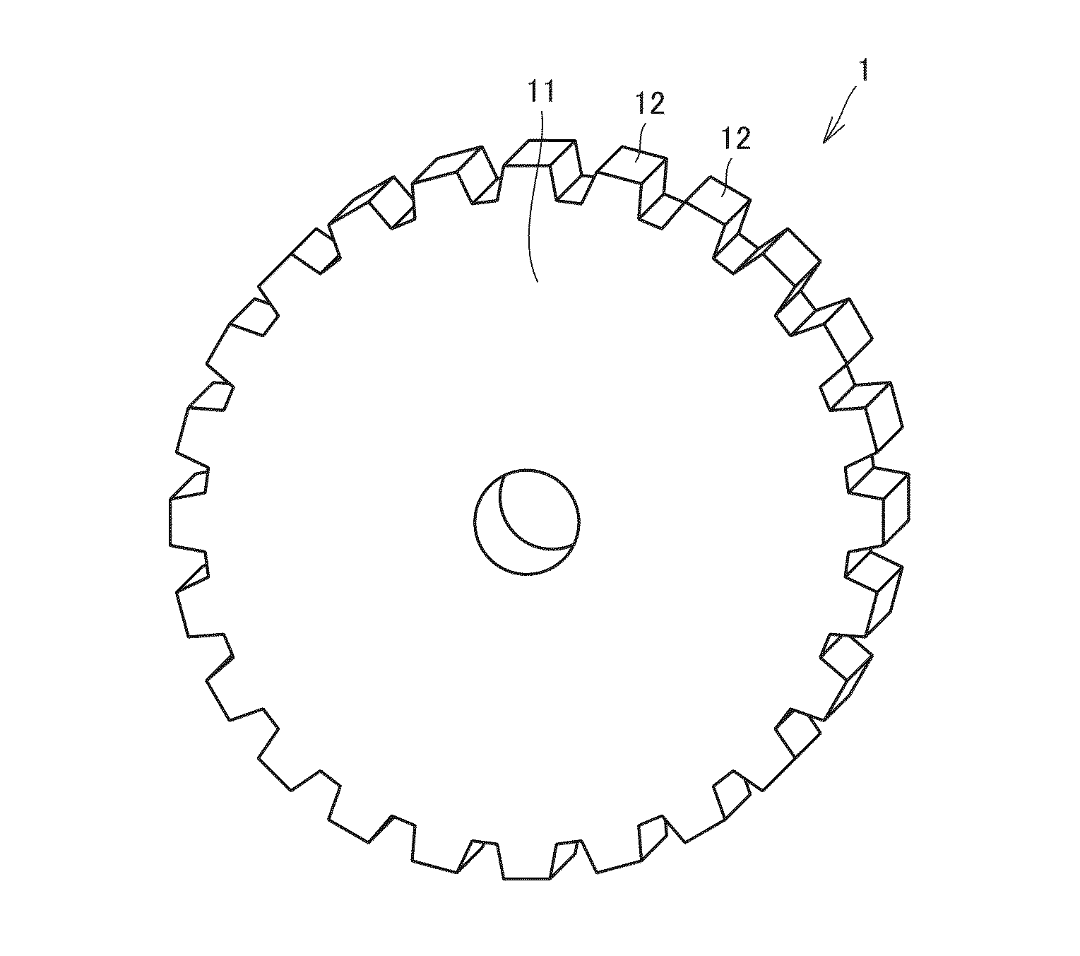
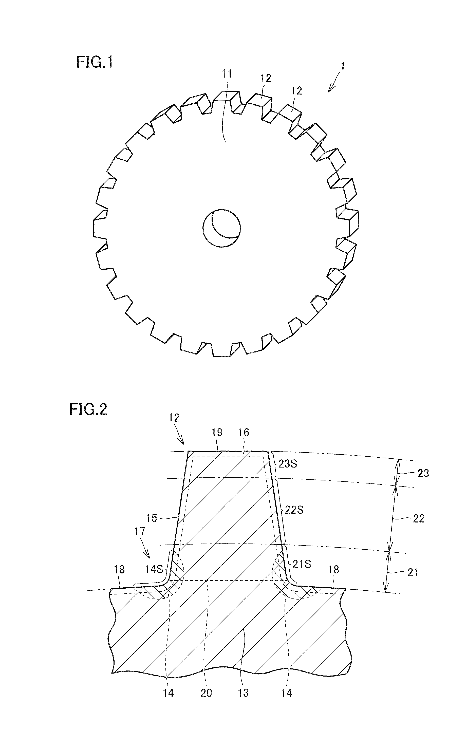
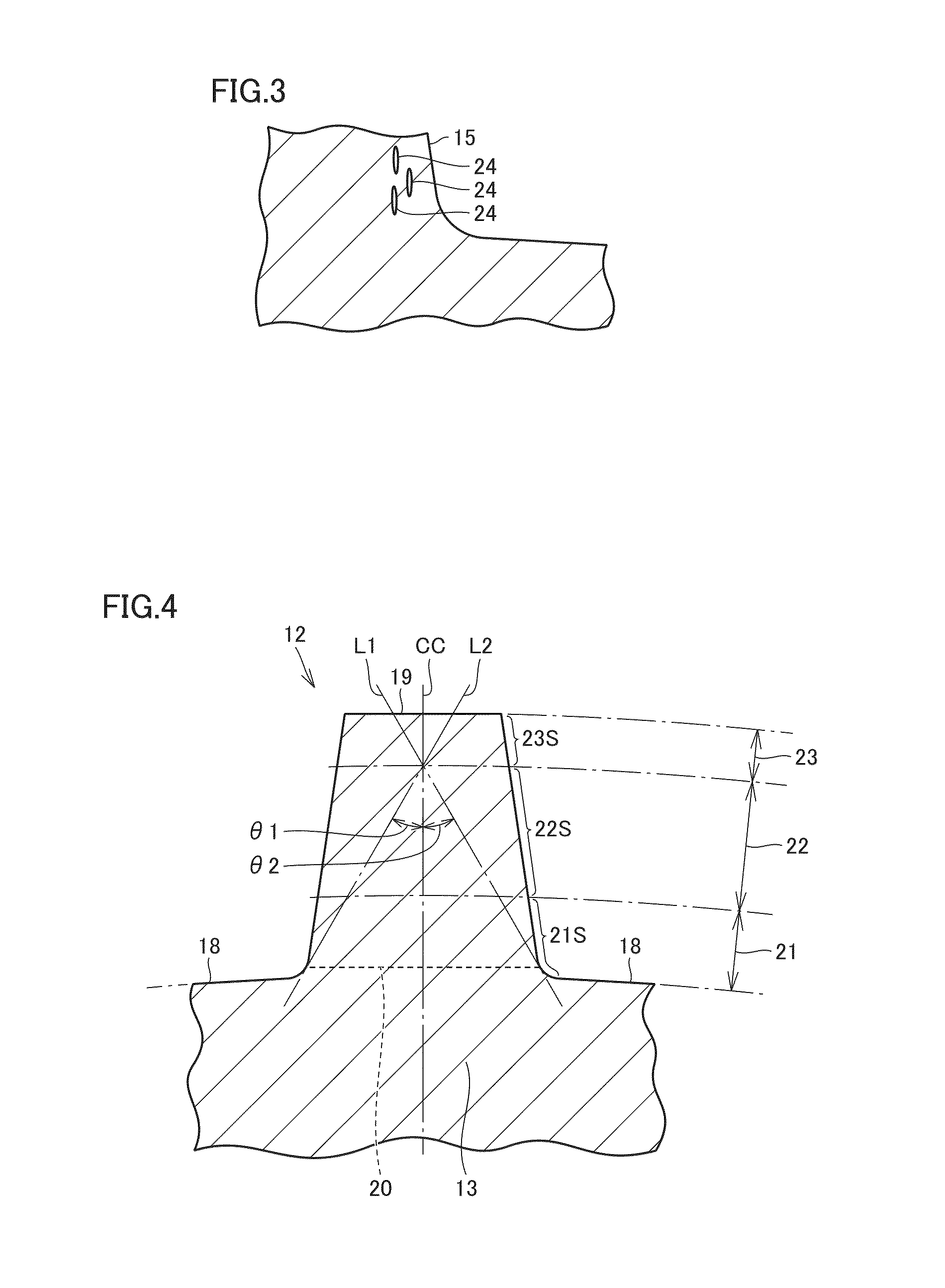
[0101]Experiments for confirming the superiority of the mechanical structure component of the present invention were carried out. The procedure of each experiment is as follows. First, three types of metal powders shown in Table 1 described below were prepared as raw material powder, and molded and sintered under the conditions shown in Table 1. After the obtained sintered body was subjected to cold rolling working by a machining margin shown in Table 2, the sintered body was heated to 870° C. in the carburizing atmosphere and maintained for 30 minutes, thereby forming a carburized layer having a thickness of 120 μm on the surface. Then, after performing quench hardening, the sintered body was heated to 150° C. and maintained for 90 minutes, thereby performing a tempering process. By the above-described procedure, a ring-shaped test piece of outer diameter φ24 mm×inner diameter φ18 mm×height 7 mm (thickness 3 mm) was fabricated. Furthermore, the above-described cold rolling working ...


PUM

PropertyMeasurementUnit
thicknessaaaaaaaaaa
porosityaaaaaaaaaa
particle diameteraaaaaaaaaa

Abstract

A sintered gear serving as a mechanical structure component is a mechanical structure component made of a metal sintered body, and includes a base region; and a high density region formed so as to include a maximum stress position at which a maximum tensile stress or a maximum shear stress is applied, and to include a surface, in which the high density region is lower in porosity than the base region. A surface hardened layer is formed in a region including the surface by performing a hardening process.

Description

TECHNICAL FIELD[0001]The present invention relates to a mechanical structure component, a sintered gear, and methods of manufacturing the mechanical structural component and the sintered gear, and more particularly to a mechanical structure component made of a sintered body, a sintered gear made of a metal sintered body, and methods of manufacturing the mechanical structure component and the sintered gear.BACKGROUND ART[0002]Gears have been conventionally used as mechanical structure components for transmitting motive power. A gear is fabricated using a melting material and the like. As a typical method of fabricating a gear made of a melting material, a gear cutting method using a hob or a rack-type cutter is known. According to the gear cutting method, a material having a disc shape (gear blank) is prepared. This gear blank has portions other than a teeth portion that are processed in advance. The gear blank is subjected to a scraping process to provide a tooth groove, thereby ach...

Claims


Application Information

Patent Timeline
Patent Type & Authority Applications(United States)
IPC IPC(8): F16H55/06B22F3/10B22F3/26F16H55/17B22F3/24B22F1/05
CPCF16H55/06F16H55/17B22F2003/248B22F3/26B22F3/10B22F3/24B22F5/08B22F3/168C22C33/0264B22F2003/241B22F2201/30B22F2207/17B22F2302/10B22F2998/10Y10T74/1987B22F1/05
Inventor OKUNO, TAKAHIROSHIMAZU, EIICHIROUARAKI, HIKARU
Owner NTN CORP
Why Eureka
Try Eureka