Polymer and organic electroluminescent element

a technology of organic electroluminescent elements and polymers, which is applied in the direction of electrical equipment, semiconductor devices, solid-state devices, etc., can solve the problems of poor driving stability, difficult lamination, and production according to wet film formation methods, and achieve excellent driving stability, high hole transporting ability and electrochemical stability. , the effect of high efficiency

Active Publication Date: 2015-02-12
MITSUBISHI CHEM CORP
View PDF2 Cites 1 Cited by
  • Summary
  • Abstract
  • Description
  • Claims
  • Application Information

AI Technical Summary

Benefits of technology

[0022]The polymer of the present invention enables lamination of layers according to a wet film formation method. In addition, the polymer has high hole transporting ability and electrochemical stability, and is therefore useful as an organic electroluminescent element material. The organic electroluminescent element produced using the polymer can be driven highly efficiently at a low voltage and is excellent in driving stability, and is therefore useful for organic EL display devices (organic EL displays) and organic EL lighting devices.

Problems solved by technology
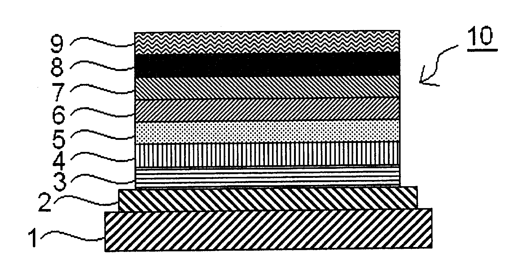
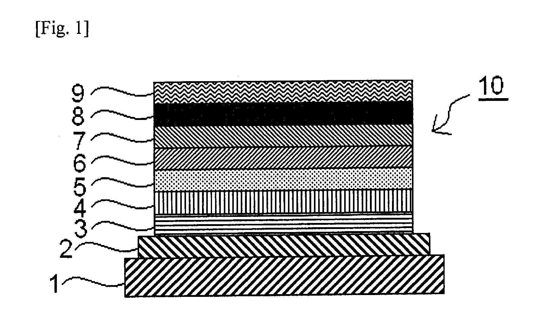
However, according to the wet film formation method, lamination is difficult.
Consequently, as compared with elements produced according to a vacuum evaporation method, those produced according to the wet film formation method are poor in driving stability, and except for a few, they could not be on a practicable level as yet.
In particular, lamination of two layers would be possible according to the wet film formation method using an organic solvent and an aqueous solvent, but lamination of three or more layers is still difficult.

Method used


Image

  • Polymer and organic electroluminescent element
  • Polymer and organic electroluminescent element
  • Polymer and organic electroluminescent element

Examples


example 1

[0409]An organic electroluminescent element was produced according to the following process.

[0410]A glass substrate 1 having, as deposited by sputtering thereon, an indium tin oxide (ITO) transparent conductive film, was patterned to have a stripe anode 2 having a stripe width of 2 mm, according to ordinary photolithography combined with hydrochloric acid etching. The thus-patterned ITO substrate was ultrasonically washed with an aqueous surfactant solution, washed with ultrapure water, ultrasonically washed with ultrapure water, and washed with ultrapure water in that order, then dried, and washed with UV ozone.

[0411]Next, a composition for forming hole injection layer was prepared, comprising an arylamine polymer represented by the following structural formula (P-1), 4-isopropyl-4′-methyldiphenyliodonium tetrakis(pentafluorophenyl)borate represented by the following structural formula (A-1) and ethyl benzoate. The composition for forming hole injection layer was applied onto the a...

example 2

[0422]A glass substrate 1 having, as deposited by sputtering thereon, an indium tin oxide (ITO) transparent conductive film, an anode 2 was patterned to have a stripe anode 2 having a stripe width of 2 mm, according to ordinary photolithography combined with hydrochloric acid etching. The thus-patterned ITO substrate was ultrasonically washed with an aqueous surfactant solution, washed with ultrapure water, ultrasonically washed with ultrapure water, and washed with ultrapure water in that order, then dried, and washed with UV ozone.

[0423]Next, a composition for forming hole injection layer was prepared, comprising an arylamine polymer represented by the structural formula (comparative polymer 2) and the structural formula (comparative polymer 3) shown below, 4-isopropyl-4′-methyldiphenyliodonium tetrakis(pentafluorophenyl)borate represented by the above-mentioned structural formula (A-1) and ethyl benzoate. The composition for forming hole injection layer was applied onto the anode...

example 3

[0440]An organic electroluminescent element was produced in the same manner as in Example 2, except that the composition for forming hole injection and the composition for forming hole transport layer were changed to the following, and tested for the operation life also in the same manner, and the result is shown in Table 8.

[0441]

Solventethyl benzoateComposition concentrationcomparative polymer 3: 2.625% by weighttarget polymer 3: 0.875% by weightA-1: 0.7% by weight

[0442]

SolventcyclohexylbenzeneComposition concentrationcomparative polymer 1: 1.0% by weight


PUM

PropertyMeasurementUnit
carbon numberaaaaaaaaaa

Abstract

The present invention relates to a polymer comprising a repeating unit containing a specific partial structure and a repeating unit containing a crosslinking group, a composition for an organic electroluminescent element comprising the polymer, and an organic electroluminescent element comprising an organic layer formed using the composition for an organic electroluminescent element by a wet film formation method.

Description

TECHNICAL FIELD[0001]The present invention relates to a polymer useful as a material for hole injection layer and / or hole transport layer of organic electroluminescent elements, to an organic electroluminescent element material comprising the polymer and to a composition for organic electroluminescent elements and an organic electroluminescent element using the polymer, as well as to an organic EL display device and an organic EL lighting device equipped with the organic electroluminescent element.BACKGROUND ART[0002]A method for formation of an organic layer in organic electroluminescent elements includes a vacuum evaporation method and a wet film formation method. A vacuum evaporation method enables easy lamination and therefore has the advantage of improving charge injection from anode and / or cathode and facilitating exciton blocking in light-emitting layer. On the other hand, a wet film formation method does not require a vacuum process and therefore has the advantage that it en...

Claims


Application Information

Patent Timeline
Patent Type & Authority Applications(United States)
IPC IPC(8): H01L51/00H01L51/50
CPCH01L51/0035H01L51/5056H01L51/5072H01L51/5088H01L51/5092C08G73/0266H10K85/111H10K85/151H10K50/17H10K50/15H10K50/16H10K50/171
Inventor BABA, TATSUSHILI, YANJUNIIDA, KOICHIROGOROHMARU, HIDEKINAKAMOTO, EMISHOUDA, TAKAYUKI
Owner MITSUBISHI CHEM CORP
Why Eureka
Try Eureka