Lithium secondary battery

a secondary battery and lithium technology, applied in the direction of batteries, sustainable manufacturing/processing, cell components, etc., to achieve the effect of reducing overvoltage, reducing overvoltage, and increasing polarization

Active Publication Date: 2015-02-19
TOYOTA JIDOSHA KK
View PDF5 Cites 21 Cited by
  • Summary
  • Abstract
  • Description
  • Claims
  • Application Information

AI Technical Summary

Benefits of technology

[0006]Generally, in a lithium secondary battery, the resistance of the positive electrode active material is higher than the resistance of the negative electrode active material, and thus a higher degree of polarization will occur during charging and discharging, causing the positive electrode to have a higher overvoltage than the negative electrode. Due to such an overvoltage, the apparent positive electrode potential detected will be higher during charging and lower during discharging. With increasing charge / discharge rate (increasing charge / discharge current), polarization will occur to a higher degree, making the positive electrode capacity smaller during high-rate charging and discharging as compared to during low-rate charging and discharging. On the other hand, the level of overvoltage (the degree of polarization) is smaller at the negative electrode as compared to at the positive electrode, and thus even at a higher charge / discharge rate, the decrease in the negative electrode capacity is relatively small (i.e. the charge / discharge rate dependence is small); and therefore, during high-rate charging and discharging, the difference between the negative electrode capacity and the positive electrode capacity (the value of the negative electrode capacity minus the positive electrode capacity) tends to be larger. Due to such a capacity difference between a positive electrode and a negative electrode, for example, a battery that has been discharged at a high rate until it reaches a prescribed discharge termination voltage may have a large amount of lithium remaining in the negative electrode active material as compared to when discharged at a low rate. When a large amount of lithium remains in the negative electrode active material, the capacity of the negative electrode active material to accept Li may decrease during charging and the battery may suffer degradation (reduced performance).
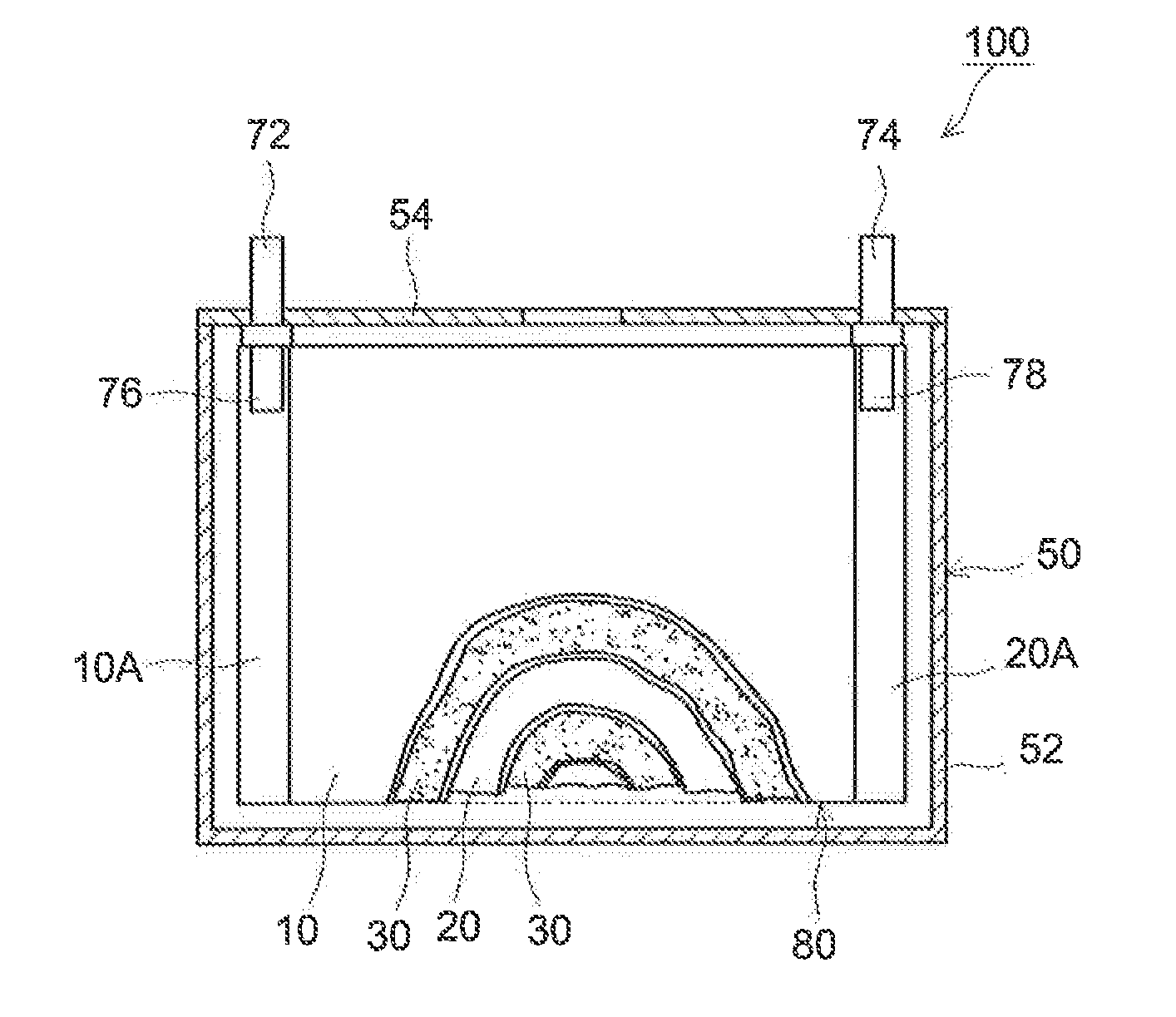
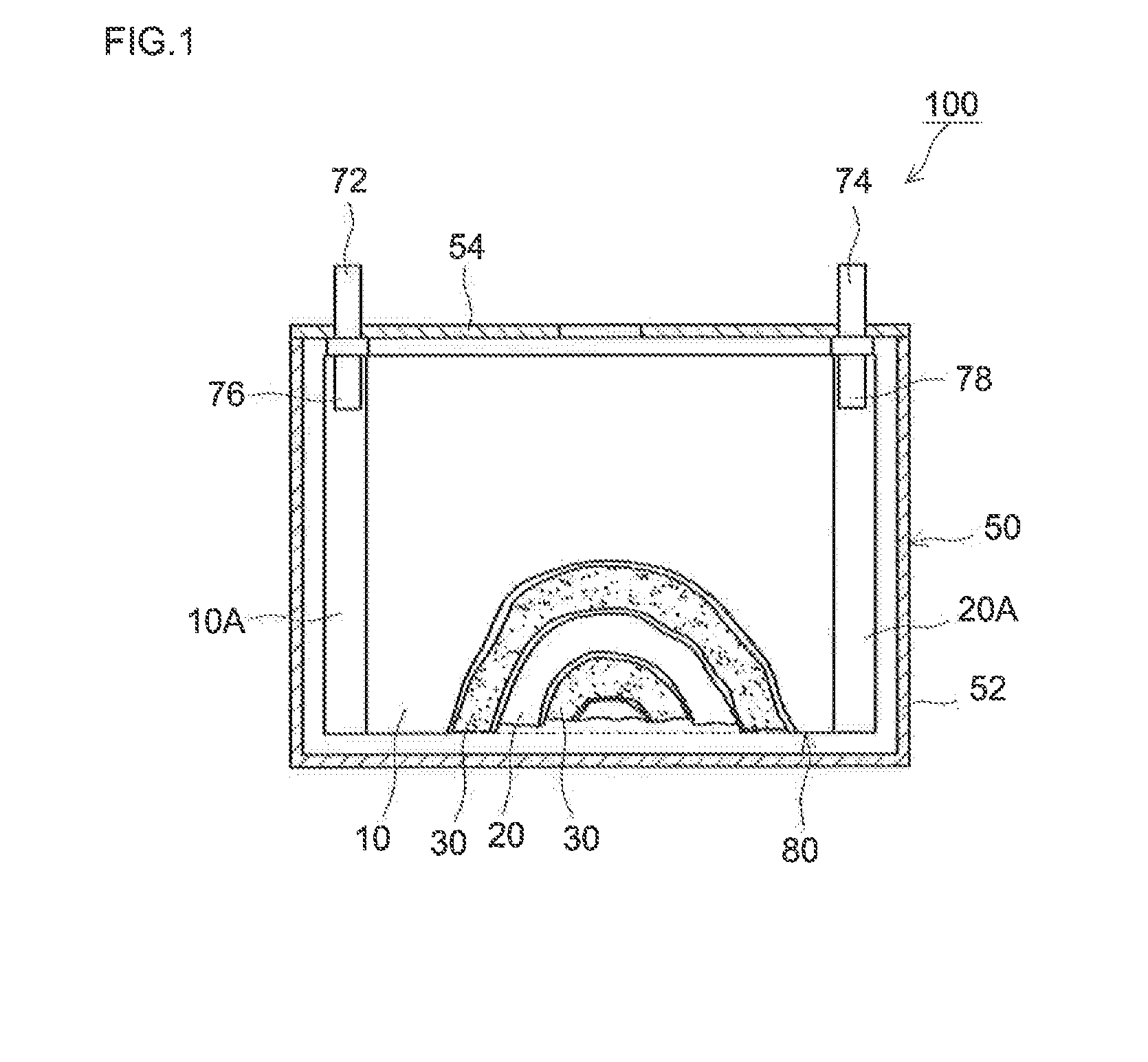
[0009]In a lithium secondary battery having such a constitution, with a Li absorber placed on the negative electrode side of the battery, part of Li may be fixed (irreversibly stored) during charging (in typical, mainly during initial charging). This allows for adjustment of the balance between the positive electrode capacity and the negative electrode capacity in view of a situation involving high-rate charging or discharging (a charging / discharging condition where the positive electrode has a higher overvoltage). For example, even when discharged at a high rate, Li inside the negative electrode active material can be more efficiently released, and thus the amount of Li remaining in the negative electrode active material when the discharge termination voltage has been reached can be reduced. Accordingly, it can prevent or lessen reduction of the capacity of the negative electrode active material to accept Li during charging following high-rate discharging and suppress degradation (e.g. an increase in the resistance) of the secondary battery. The Li absorber is added to the inorganic filler and placed in the inorganic porous material layer, making it easy to put a suitable amount of the Li absorber.
[0013]In a preferable embodiment of the lithium secondary battery disclosed herein, the positive electrode active material layer comprises, as the positive electrode active material, a lithium transition metal oxide having a layered structure. According to such an embodiment, the effects by applying the present invention can be produced to a greater extent and a high performance battery having excellent durability to high-rate charge / discharge cycles can be realized.
[0014]The amount of the Li absorber can be, for instance, 20 parts by mass or less (typically 0.5 to 20 parts by mass) relative to 100 parts by mass of the positive electrode active material. When the amount of the Li absorber is excessively large relative to the amount of the positive electrode active material, the initial battery capacity may tend to be low. When the amount of the Li absorber is excessively small, the effects of the Li absorber (e.g. an effect to increase the durability to high-rate charge / discharge cycles) may diminish.
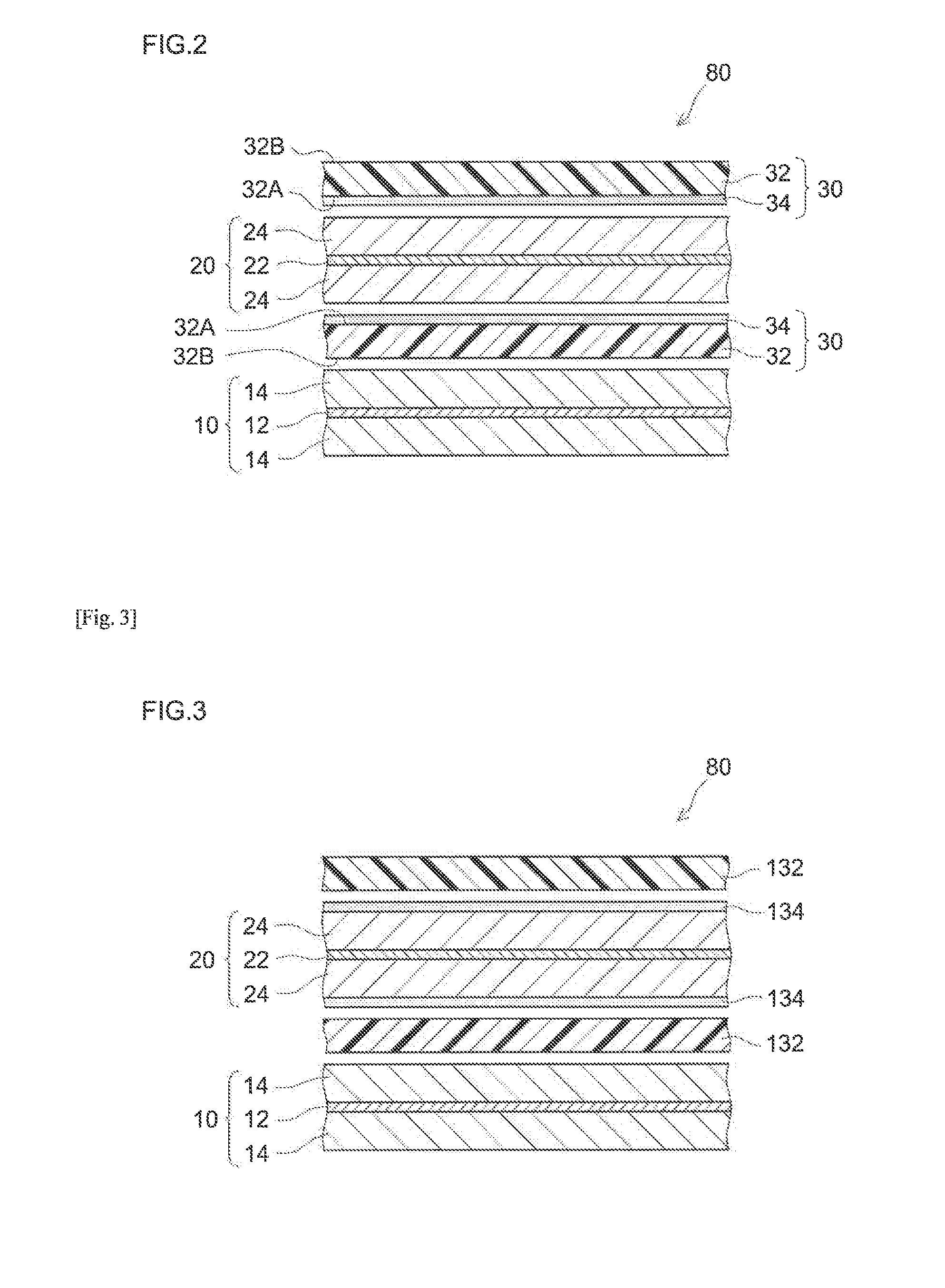
[0015]The inorganic porous material layer should just be placed between the organic porous material layer and the negative electrode active material layer. For example, it may be in such a form that the inorganic porous material layer is retained on the negative electrode-facing surface of the organic porous material layer, in such a form that it is retained on the surface of the negative electrode active material layer, or in an independent sheet form, etc. In a preferable embodiment, the inorganic porous material layer is retained on the negative electrode-facing surface of the organic porous material layer. According to such an embodiment, the use of the inorganic porous material layer can increase the heat resistance of the organic porous material layer (e.g. thermal contraction is suppressed).
[0017]A lithium secondary battery disclosed herein can exhibit good durability even in a use mode involving high-rate charging or high-rate discharging as described above, and thus it is suitable, for instance, as a battery loaded on a vehicle. Therefore, the present invention can provide a vehicle (e.g. an automobile) comprising the lithium secondary battery, (typically a lithium-ion secondary battery) as a vehicle-driving power supply (typically as a power source in a hybrid vehicle or an electric vehicle).

Problems solved by technology

When a great deal of thermal contraction occurs, a local tensile stress may be applied to the sheet to open a hole or the surface area of the sheet may shrink, possibly causing the two electrodes to contact each other to form a new short-circuit spot.

Method used


Image

  • Lithium secondary battery
  • Lithium secondary battery
  • Lithium secondary battery

Examples


example 1

[0088](Fabrication of Heat-Resistant Separator)

[0089]Alumina powder (0.6 μm average particle diameter; available from Sumitomo Chemical Co., Ltd.; “AKP3000”) as an inorganic filler, an acrylic binder (a Zeon Corporation product) and CMC (available from Dai-ichi Kogyo Seiyaku Co., Ltd.; trade name “BSH6”) were mixed with ion-exchanged water as a solvent at a Al2O3:binder:CMC ratio of 98:1.3:0.7, to a 50% non-volatile content (NV). For the mixing, a disper-mill (available from ROBO MICS) was used. The mixing was performed at 5000 rpm for 15 minutes. A slurry (dispersion) for forming inorganic porous material layers was thus prepared.

[0090]To a face (first face) of a single-layer polyethylene porous sheet (available from Ube Industries, Ltd., 20 μm thick, 45 vol % porosity, 400 sec / 100 mL air permeability; “porous PE sheet” hereinafter), the slurry prepared above was applied with a gravure coater and allowed to dry at 70° C. to form an inorganic porous material layer. The applied amoun...

example 2

[0099]NiO powder (400 mesh nickel oxide available from Alfa Aesar pulverized in a planet ball mill to about 0.5 μm average particle diameter) as a Li absorber was included in the inorganic porous material layer of the heat-resistant separator in Example 1. More specifically, at a Al2O3:NiO:binder:CMC ratio of 98:85:1.3:0.7, they were mixed with ion-exchanged water to a 50% NV to prepare a slurry for forming inorganic porous material layers. The slurry was applied to a first face of the porous PE sheet to an applied amount of 1.39 times the mass applied in Example 1 and allowed to dry. Otherwise, in the same manner as Example 1, a heat-resistant separator was fabricated. Using the heat-resistant separator, a laminated cell was constructed. The heat-resistant separator used for fabricating the cell according to the present example contained, in the inorganic porous material layer facing the negative electrode, NiO in an amount equivalent to 10% by mass of the positive electrode active...

example 3

[0100]An inorganic porous material layer-firming slurry was prepared at a Al2O3:NiO:binder:CMC ratio of 98:102:1.3:0.7 and the amount of the slurry applied based on the solid content was 2.02 times the mass applied in Example 1. Otherwise, in the same manner as Example 1, a laminated cell was constructed. The heat-resistant separator used for fabricating the cell according to the present example contained NiO in an amount equivalent to 12% by mass of the positive electrode active material in the inorganic porous material layer facing the negative electrode.


PUM

PropertyMeasurementUnit
temperatureaaaaaaaaaa
thicknessaaaaaaaaaa
densityaaaaaaaaaa

Abstract

This invention provides a lithium secondary battery which degrades less upon high-rate charge / discharge cycles (thus durable). The lithium secondary battery comprises positive electrode 10 having positive electrode active material layer 14, negative electrode 20 having negative electrode active material layer 24, organic porous material layer 32 placed between positive electrode active material layer 14 and negative electrode active material layer 24, inorganic porous material layer 34 placed between organic porous material layer 32 and negative electrode active material layer 24. Inorganic porous material layer 34 comprises an inorganic filler that does not store lithium at a potential higher than the lithium-storing potential of the negative electrode active material layer, and a Li absorber that irreversibly stores lithium at a potential higher than the lithium storing potential.

Description

TECHNICAL FIELD[0001]The present invention relates to a lithium secondary battery.BACKGROUND ART[0002]Lithium secondary batteries are used as power supplies loaded on electrically-driven vehicles, or as power sources installed in PCs and other mobile terminals, etc. In particular, lightweight lithium-ion secondary batteries with high energy densities are becoming increasingly important as high-power power supplies loaded on vehicles (e.g. power sources for driving motors connected to drive vehicle wheels).[0003]A typical lithium secondary battery includes a separator which separates a positive electrode active material layer and a negative electrode active material layer. The separator prevents a short circuit associated with direct contact between these two active material layers, and with the pores of the separator being impregnated with an electrolyte solution, it also serves to form ion-conducting paths (conduction channels) between the two electrodes. Typical examples of a sepa...

Claims


Application Information

Patent Timeline
Patent Type & Authority Applications(United States)
IPC IPC(8): H01M2/16H01M10/052H01M50/403H01M50/417H01M50/423H01M50/431H01M50/449H01M50/457H01M50/491
CPCH01M2/1686H01M2220/20H01M2/166H01M10/052H01M4/587H01M10/0525H01M10/0587H01M10/4235H01M4/505H01M4/525H01M50/431H01M50/403H01M50/449H01M50/491H01M50/457H01M50/423H01M50/417Y02E60/10Y02P70/50Y02T10/70H01M50/446
Inventor KINOSHITA, KOJISHIRANE, TAKAYUKI
Owner TOYOTA JIDOSHA KK
Why Eureka
Try Eureka