
Blast furnace with top-gas recycle

a blast furnace and top gas technology, applied in blast furnaces, climate sustainability, metal processing, etc., can solve the problems of reducing the efficiency of blast furnaces, and reducing the number of blast furnaces. the effect of reducing the carbon dioxide emissions per ton of iron produced

Inactive Publication Date: 2015-03-12
HYL TECH SA DE CV
View PDF3 Cites 6 Cited by
  • Summary
  • Abstract
  • Description
  • Claims
  • Application Information

AI Technical Summary

Benefits of technology

This patent text describes a method and apparatus to improve the operation of a blast furnace in several ways. The method involves using oxygen instead of air to avoid nitrogen content in the top gas, cleaning the top gas of dust and adjusting the ratio of H2 / CO, cooling the top gas to remove water, removing CO2 from the top gas, and heating the resulting reducing gas stream to a high temperature before feeding it back to the blast furnace. The technical effects include decreased coke consumption and carbon dioxide emissions, minimized problems with heating recycled top gas, and upgrading of the resulting top gas for better utilization in the blast furnace.

Problems solved by technology

One of the problems to be solved is the nitrogen content of the top gas originating from the air blast.
Another problem is the need for reheating the recycled gas prior to its being fed into the reduction area of the blast furnace, because the high content of CO causes carbon formation which may cause clogging and fouling of the reheating equipment and of the heating path equipment.
This process has the drawback of needing a cryogenic plant for separating nitrogen contained in the top gas.
However, the process of this patent is limited in the amount.

Method used


Image

  • Blast furnace with top-gas recycle
  • Blast furnace with top-gas recycle

Examples


Embodiment Construction

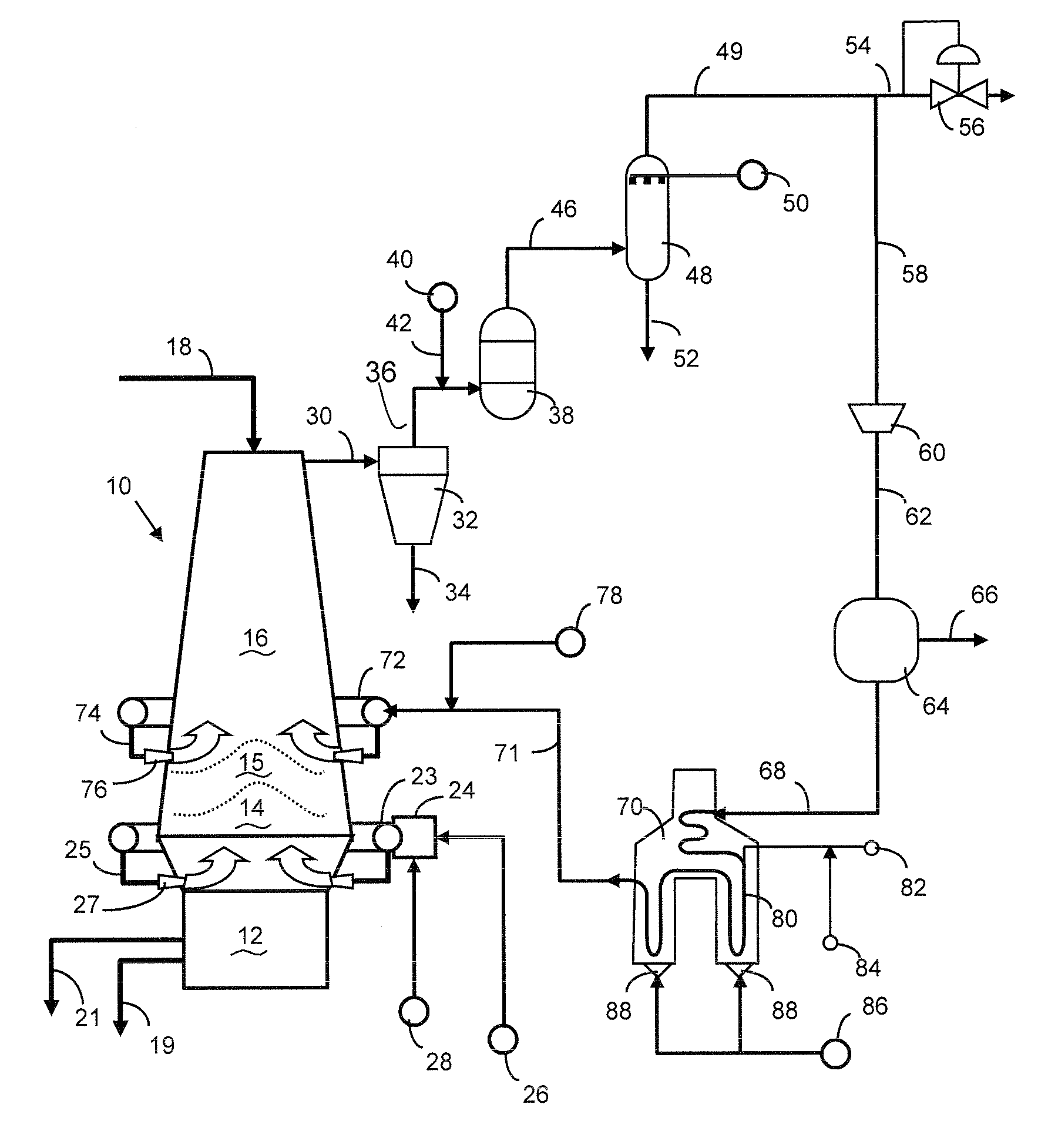
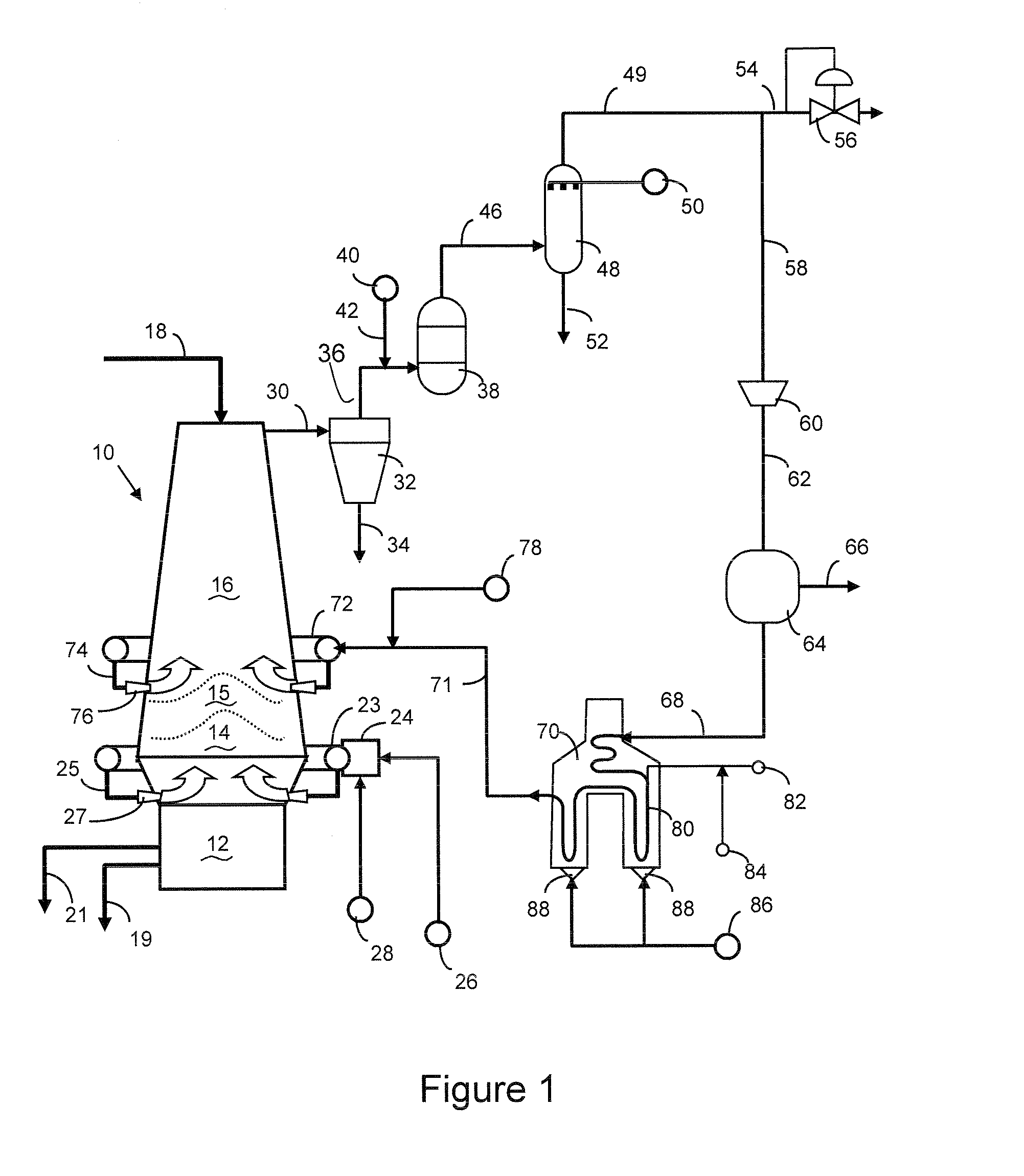
[0025]Referring to FIG. 1, numeral 10 generally designates a blast furnace having a crucible section 12 where molten iron and slag are collected, a blast section 14 where the oxygen containing gases are introduced for carrying out the combustion of coke, and a shaft section 16 where iron ore particles in the form of sinter, pellets or lumps and mixtures thereof are charged along with coke, limestone and other fluxes 18, and next the iron oxides are reduced to wustite and finally to metallic iron as is known in the art. Molten iron 19 and slag 21 are periodically tapped from the bottom zone 12 of blast furnace 10.

[0026]Oxygen from a source 26 of industrial purity, instead of air, is fed to mixing device 24 where a temperature moderating agent is fed from a source 28 for preventing the flame temperatures from reaching excessively high levels and therefore from damaging the blast nozzles in tuyeres 27. The temperatures moderating agents 28 may be for example, steam, carbon dioxide, oil...


PUM

PropertyMeasurementUnit
Temperatureaaaaaaaaaa
Pressureaaaaaaaaaa

Abstract

A blast furnace where coke is combusted with oxygen, instead of air, and where a top gas comprising CO, CO2, H2, and without excess nitrogen is withdrawn from the upper part of the blast furnace, cleaned of dust, the H2 / CO volume ratio adjusted to between 1.5 to 4.0 in a water shift reactor, water and CO2 are removed (increasing its reduction potential), heated to a temperature above 850° C. and fed back to the blast furnace above where iron starts melting (thereby increasing the amount of metallic iron reaching the dead-man zone and decreasing the amount of coke used for reduction). Also carbon deposit problems caused by heating the CO-containing recycled gas are minimized by on-line cleaning of the heater tubes with steam without significantly affecting the reduction potential of the recycled reducing gas.

Description

FIELD OF THE INVENTION[0001]The invention relates to the field of the iron and steel industry, more particularly to a more efficient method and plant for production of liquid iron in blast furnaces, with reduced coke consumption by recycling upgraded top gas with an adjusted H2 / CO ratio.BACKGROUND OF THE INVENTION[0002]In a blast furnace producing pig iron, iron ore is charged together with coke and fluxes. A hot air blast is injected through tuyeres at the bottom of the furnace, thereby generating heat by the combustion of carbon in the coke which melts down the charge. Periodically liquid iron and slag are tapped from the furnace. The combustion gases flow up through the furnace and reduce the iron oxides, and exit the furnace as a stream of dust-laden hot gas which from heat is recovered for preheating the air blast, and which is then normally used as fuel in other areas of the steel plant.[0003]Metallurgical coke is needed in the charge of a blast furnace because this material (...

Claims


Application Information

Patent Timeline
IPC IPC(8): C21B5/06C21B7/16C10K3/04F27D17/00C10K1/02C10K1/04C21B7/00C21B7/22
CPCC10K3/04C21B2100/02C21B2100/04C21B2300/02C21B5/06C10K1/04C21B7/16C21B7/22F27D17/008F27D17/001C10K1/02C21B7/002B01D2257/504B01D2258/025C10K1/005C21B5/00C21B2100/24C21B2100/282F27B1/10F27B1/18F27B1/24Y02P10/122Y02P10/20Y02P10/25
Inventor GARZA-DAVILA, JOSE-CARLOSBECERRA-NOVOA, JORGE-OCTAVIODUARTE-ESCARENO, PABLO-ENRIQUE
Owner HYL TECH SA DE CV
Learn More