Air-to-air heat exchanger bypass for wet cooling tower apparatus and method

a technology of air-to-air heat exchanger and cooling tower, which is applied in the direction of lighting and heating apparatus, liquid degasification, separation processes, etc., can solve the problems of moisture in the plume being frozen, low lying fog, and moisture in the plume being created by moisture, so as to reduce the heat content of the air stream

Active Publication Date: 2015-03-12
SPX COOLING TECH
View PDF1 Cites 6 Cited by
  • Summary
  • Abstract
  • Description
  • Claims
  • Application Information

AI Technical Summary

Benefits of technology

[0021]In another aspect of the invention, a method for reducing the heat content of an air stream in a cooling tower is provided, comprising the steps of: directing a first air stream through a first set of passageways of a first heat exchanger module; directing a second air stream through a separate, second set of passageways of the first heat exchanger module; directing a third air stream through a third set of passageways of a second heat exchanger module and through a first bypass path; directing a fourth air stream through a separate, fourth set of passageways of the second heat exchanger module and through a second bypass path; and transferring heat from said first air stream into said second air stream.

Problems solved by technology

A recognized drawback to cooling towers, however, is that under certain atmospheric conditions a plume can be created by moisture from the heated water source evaporating into the air stream being carried out of the top of the cooling tower.
Where the cooling tower is very large, as in the case of power plants, the plume can cause low lying fog in the vicinity of the cooling tower.
The plume can also cause icing on roads in the vicinity of the cooling tower where colder temperatures cause the moisture in the plume to freeze.
The separate heat exchanger reduces the efficiency of the cooling tower and thus should only be employed when atmospheric conditions exist in which a plume would be created by the cooling tower.
While the foregoing systems provide useful solutions to the wet cooling tower plume problem, they all require the construction of a complex and costly wet and dry air heat transfer mechanism.
Moreover, when such towers operate in “non-plume” abatement mode, more fan energy is expended pull the air through the heat exchange packs, causing the operational costs to the tower to significantly increase.
Another recognized problem with cooling towers is that the water used for cooling can become concentrated with contaminates.
If chemicals are added to the cooling water to treat the water these chemicals can become highly concentrated which may be undesirable if released into the environment.
If seawater or waste water is used to replace the evaporated water, a common practice where fresh water is not available or costly, salts and solids in the water can also build up in the cooling water circuit As these contaminants become more concentrated they can become caked in between the thin evaporating sheets diminishing the towers cooling efficiency.
While this prevents the contaminants in the cooling tower water from becoming too concentrated, there may be environmental consequences to discharging water during the blowdown process.
A separate problem that has been noted is the desalination of sea water, and purification of other water supplies, to create potable drinking water.
While these towers conserve water, thermal performance of the cooling tower typically is affected as the cooling can become inefficient with respect to heat exchange.
The typical remedies for increased thermal performance are to increase fan power which increases operating costs, to increase the plan area of the tower which increases capital costs, or both.

Method used


Image

  • Air-to-air heat exchanger bypass for wet cooling tower apparatus and method
  • Air-to-air heat exchanger bypass for wet cooling tower apparatus and method
  • Air-to-air heat exchanger bypass for wet cooling tower apparatus and method

Examples


Embodiment Construction

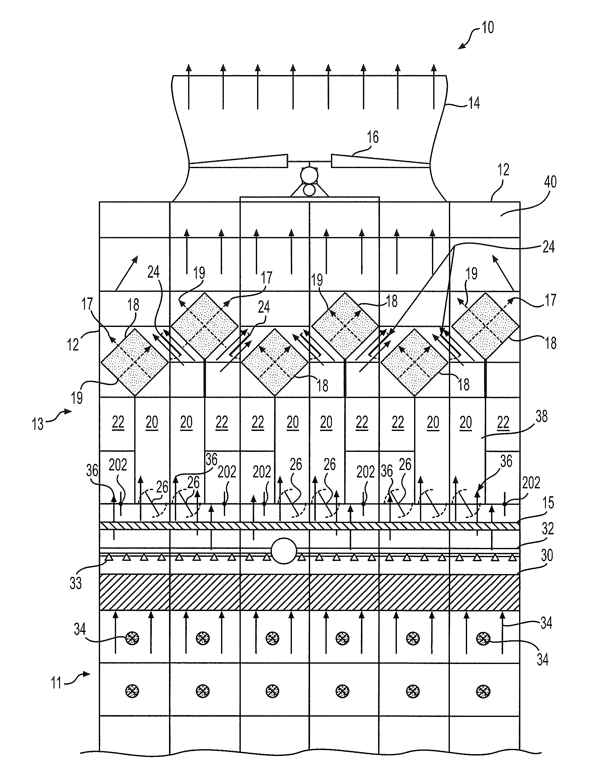
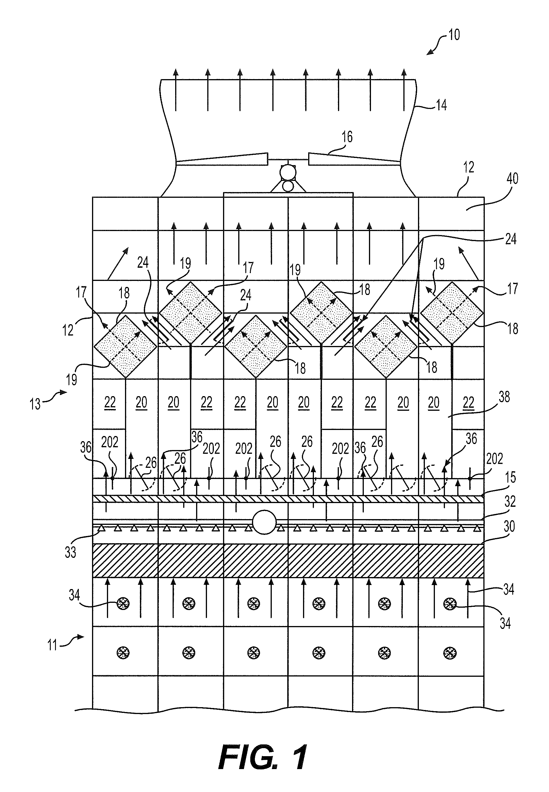
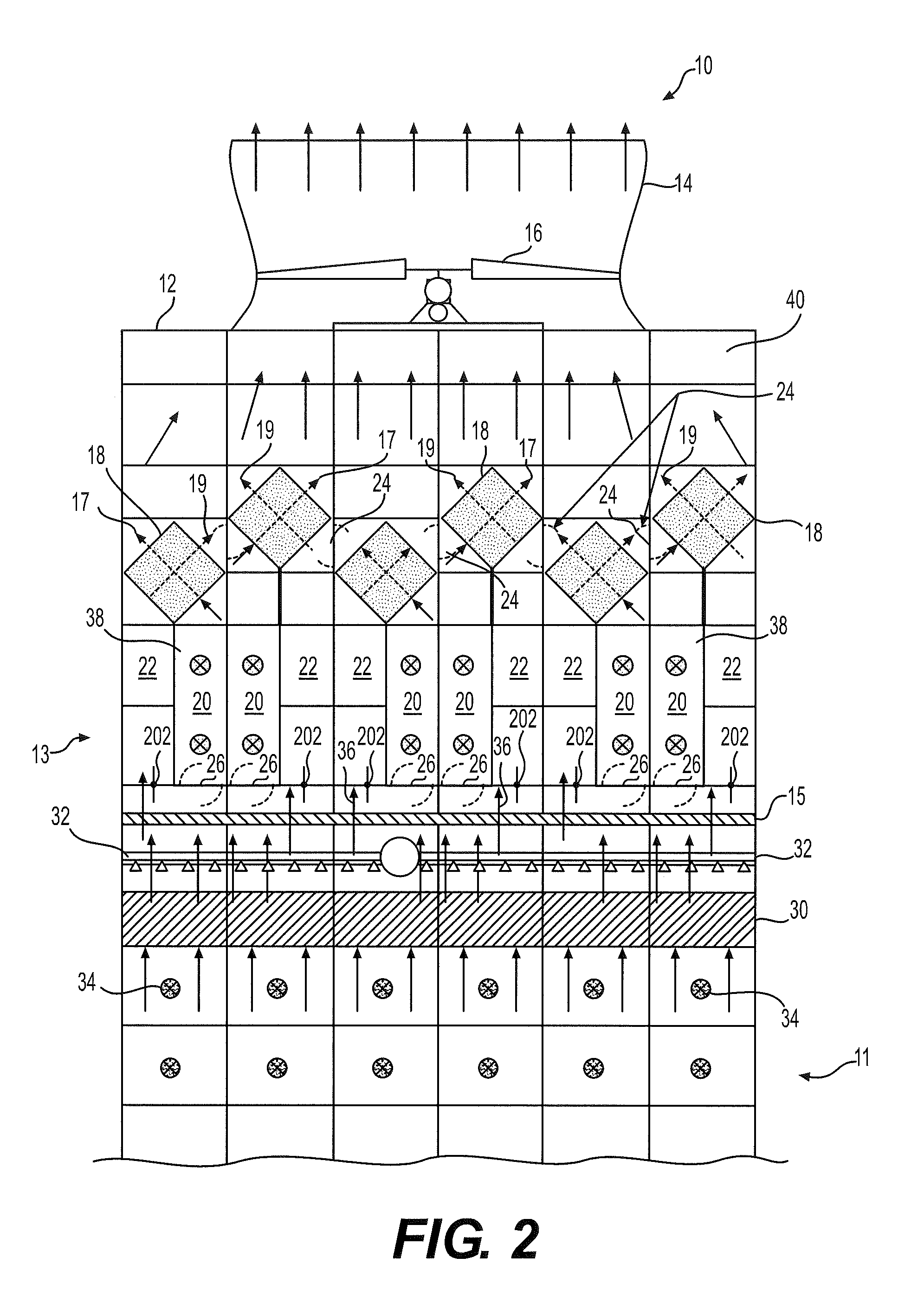
[0038]Referring now to the figures wherein like reference numerals indicate like elements, FIGS. 1-3 depict a cooling tower apparatus, generally designated 10 having a support frame assembly 12 and a shroud 14 within which an air current generator (axial fan) 16 operates. The cooling tower 10 is generally comprises a wet, direct cooling section 11 and a dry, indirect cooling section 13 that are separated by an eliminators 15. The cooling tower 10 includes a plurality of heat exchanges modules 18 positioned and oriented in a series, each in fluid communication with dry air ducts 20 and wet air ducts 22. The individual exchanger modules 18 preferably have a generally diamond shape or diamond configuration however may alternatively be any functional geometry. As previously discussed, cooling tower 10 also includes a series of ambient or dry air ducts 20 each having air inlets or dampers 38, along with a series of warm air or wet air ducts 22 through which warm, moist air, or effluent, ...


PUM

PropertyMeasurementUnit
thicknessaaaaaaaaaa
thicknessaaaaaaaaaa
temperatureaaaaaaaaaa

Abstract

A cooling tower having an evaporative media along with a liquid distribution system that distributes hot liquid over the evaporative media. The cooling tower includes a pair of heat exchanger modules that each have a first set of passageways in fluid communication with a first flow duct and a second set of passageways in fluid communication with a second flow duct. The heat exchanger module transfers heat from a first air stream into a second air stream. The cooling tower further includes a first bypass flow path that extends between the first heat exchanger module and the second heat exchanger module whereby a bypass door regulates airflow there through.

Description

[0001]CROSS-REFERENCE[0002]This application is related to U.S. Provisional Patent Application Ser. No. 61 / 877,005, titled “AIR-TO-AIR HEAT EXCHANGER BYPASS FOR WET COOLING TOWER APPARATUS AND METHOD,” filed Sep. 12, 2013, the disclosures of each which are hereby incorporated by reference in their entirety.FIELD OF THE INVENTION[0003]The present invention relates generally to plume abatement for cooling towers or other heat rejection devices and the like. More particularly, the present invention relates to method and apparatus for a cost effective and efficient plume abatement in cooling towers.BACKGROUND OF THE INVENTION[0004]In electricity generation using steam driven turbines, water is heated by a burner to create steam which drives a turbine to creates electricity. In order to minimize the amount of clean water necessary for this process, the steam must be converted back into water, by removing heat, so that the water can be reused in the process. In air conditioning systems for...

Claims


Application Information

Patent Timeline
Patent Type & Authority Applications(United States)
IPC IPC(8): F28F25/12F28F25/02F28C1/14
CPCF28F25/12F28F25/02F28C1/14F28C1/16Y02B30/70Y10S165/135Y10S165/327Y10S165/355Y10S165/90F28C1/00F28F2210/04
Inventor MOCKRY, ELDON F.MORTENSEN, KENNETH P.HICKMAN, CRAIG J.
Owner SPX COOLING TECH
Why Eureka
Try Eureka